IS--1379
February 2015
Page 2 of 4
STEP 1 CABLE TRAINING
A. Train cable to ensure slack for ease of operation.
B. Use one of the two following methods to provide an extra length of concentric neutral wires or grounding
braid wire to facilitate the connection of the neutral to the tank ground and the operation of the hotstick:
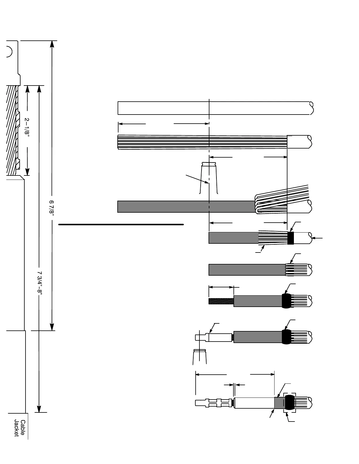
1. Mark the centerline of the bushing with tape and pull extra cable to 24--26” beyond the centerline.
Remove the outer jacket 7 3/4” to 8” back from centerline.
2. Proceed to step ”D” and connect the neutral wires to the tank ground with a jumper or grounding braid.
C. Unwrap the neutral wire back past the bushing centerline.
D. Cut excess cable squarely at the centerline of the bushing.
STEP 2 CABLE PREPARATION
(Use cable cut back template (to the left) for
dimensional guide.)
A. Wrap one strip of mastic, stretching slightly,
around jacket.
B. Bend all of the neutral wires straight back
over the mastic and along the cable. Press
the wires into the mastic.
C. Wrap the second strip of mastic completely
around the outer jacket, overlapping the
neutral wires imbedded into the first mastic
strip. Use the third strip of mastic, if needed,
to build--up the outer diameter in the area of
the first mastic location. Cover all mastic with
vinyl tape.
D. Remove insulation shield and insulation
from the cable end. Cut squarely taking care
not to nick conductor.
E. Wire brush bare aluminum conductors and
immediately install compression lug. Rotate
to spread inhibitor.
Position compression lug so the CONTACT
THREADED HOLE ALIGNS WITH THE
BUSHING BORE. (Refer to crimp chart
packaged with compression lug for
recommended crimp tool information.) Start
crimp at the crimp line mark. Rotate 180
0
each successive crimp. Carefully wipe
excessive inhibitor from the outside of the
lug and cable.
F. Remove insulation shield as shown. Bevel
insulation end 1/8” max.
G. Thoroughly clean insulation to remove all
traces of conductive residue.
7---3/4”--8”
2---1/8”
Start Crimp Here
First Mastic
Align lug thread
to bushing bore
6---7/8”
1/8” Max.
Bevel
Insulation
Insulation
Shield
Straight, Smooth & Squared
Do not cut or nick insulation
Second Mastic
Insulation Shield
Imbed Wires into
First Mastic Strip
Outer
Jacket
Third Mastic
Vinyl Tape
Extra Length of Wires/Braid
24” -- 26”
Bushing
Centerline
Wires/Braid not shown
Bent Back for Clarity
7---3/4”--8”
Jacketed Cable
 Loading...