Electrical Test lnstruments MAC-20
Retrofit Package
Section
ll -
Detailed
Description
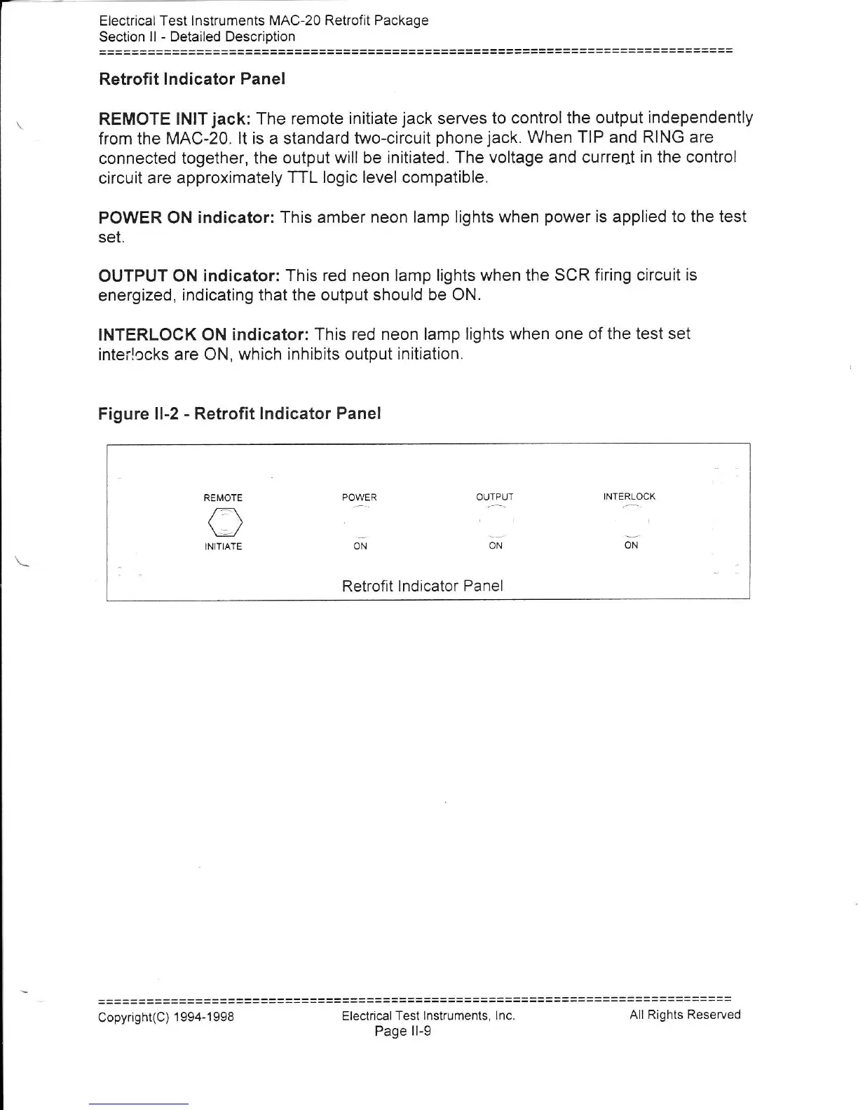
Retrofit lndicator Panel
REMOTE
lNlT
jack:
The remote
initiate
jack
serves to control
the output
Independently
from the
MAC-20. lt is a standard
two-circuit
phone
jack.
When TIP and
RING are
connected together, the output
will be initiated.
The voltage and current
in the control
circuit
are approximately
TTL logic level compatible.
POWER ON
indicator: This amber neon lamp
lights when
power
is applied
to the test
set.
OUTPUT
ON indicator:
This red neon lamp lights when the
SCR firing circuit
is
energized,
indicating that the output
should be ON.
INTERLOCK ON
indicator: This
red neon lamp lights when one
of the test set
interlccks are
ON, which inhibits output
initiation.
Figure
ll-2
-
Retrofit lndicator
Panel
REMOTE
()
INITIATE
POWER
Orl
OUTPUT
ON
INTERLOCK
ON
Retrofit
I ndicator Panel
Electric€l
Test lnstruments,
lnc.
Page ll-9
Copyright(C)
1 994-1998
All Rights Reserved