Do you have a question about the Electro Industries/GaugeTech Nexus 1262 and is the answer not in the manual?
Discusses common connections for three-phase power transmission and distribution.
Explains delta-connected services, their configurations, and phase-to-ground voltage characteristics.
Details Blondell's theorem for polyphase metering and its application in modern digital meters.
Differentiates between power, energy, and demand, explaining their measurement and units.
Explains reactive power, power factor, and their calculation methods.
Describes harmonic distortion caused by non-linear loads and its impact on waveforms.
Defines power quality problems and their potential causes originating from utility or customer equipment.
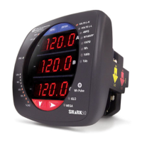
Introduces the Nexus meter as a polyphase revenue meter for advanced metering requirements.
Explains the Accu-Measure technology for advanced metering, including sampling and calculation processes.
Details advanced features of the meter, including revenue billing and time-of-use capabilities.
Describes the meter's full four-quadrant power and energy measurement and demand features.
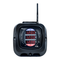
Outlines the meter's communication ports and I/O capabilities, including standard and optional connections.
Discusses the graphical LCD display, its features, and programmability for viewing data.
Describes additional switches and signals that aid in using the unit, such as mode and test buttons.
Details the supported S-Based meter forms for socket meters and switchboard meter options.
Presents the accuracy specifications for various measurements of the Nexus® 1262/1272 meter.
Provides an overview of sense inputs, voltage specifications, isolation, and sensing technologies.
Explains the operating information represented on the meter's nameplate, including serial and model numbers.
Describes basic meter operation, including the function of switches and indicators like mode, reset, and test buttons.
Details the graphical LCD display, its programmable features, and mode details for accessing information.
Provides instructions on how to find the meter's display firmware versions using CommunicatorPQA software.
Illustrates the navigation map for the Nexus 1262/1272 meter's programmable display.
Guides users on how to use the Display Configurator software to customize meter screens and display layouts.
Explains how to use the base programmable display, including assigning pre-defined screens and configuring view modes.
Lists and describes pre-defined display screens available for the meter, offering user-friendly features like large digits.
Introduces the LED and LCD display features used for meter calibration and testing.
Describes the Test Pulse LED's function for calibration pulses and how to program it.
Explains the LCD display's role in Test Mode, showing accumulated energy and phase voltage indicators.
Details Test Mode, allowing meter testing without disturbing billing data or setting new demands.
Provides instructions on how to enter Test Mode, which may involve bypassing security systems.
Explains how quantities are calculated and displayed in Test Mode, noting format changes for higher resolution.
Describes the use of Preset Accumulators screens for adjusting values when a monitor is out of service or replacing a meter.
Outlines the three ways to exit Test Mode, including button press, time-out timers, and their operational differences.
Shows serial communication options, including RS232 via optical port and RS485 for multiple devices.
Explains how to communicate with the meter via its optical port using a magnetic optical communications coupler.
Discusses RS485 communication, its bus capabilities, and connection distances.
Details the fundamentals of a 2-wire RS485 connection, including shield and +/- terminal connections.
Explains the Unicom 2500's role in providing RS485/RS232 conversion for communication.
Describes the RJ45 connection for Ethernet using the INP200 option, conforming to IEEE 802.3 standards.
Details the INP202 option, an extension of INP200, featuring a built-in modem for combined modem and Ethernet capabilities.
Guides connecting communication wires from the meter to an LED Display using RS485 cable.
Describes the communication ports on I/O modules, including female/male RS485 and I/O ports.
Explains connecting the meter to I/O modules using an RS485 cable harness.
Details steps to determine power needs for I/O modules, referencing VA ratings and power sources.
Explains remote communication using modems over telephone lines via RS485, recommending Modem Manager.
Guides on programming modems for remote communication, listing essential settings and recommending EIG's Modem Manager.
Provides selected modem strings for communication, listing configurations for different modem models.
Describes the use of built-in High Speed Inputs for status detection or pulse counting.
Explains IRIG-B connections for synchronizing meter time-stamping with GPS satellite systems.
Discusses time synchronization alternatives including IRIG-B, Line Frequency, Internal Clock Crystal, and DNP Time.
Details the INP200 Ethernet option, a customizable web server for real-time data access via the Internet.
Describes the hardware components of the INP200 Ethernet option, enabling network connectivity.
Guides on connecting the meter with the INP200 Ethernet option using standard RJ45 cables.
Explains the INP202 option, extending INP200 features with a built-in modem for combined modem and Ethernet capabilities.
Outlines the hardware overview of the INP202 option, which includes modem and Ethernet capabilities.
Details the cable connections required for the INP202 option, including RS485, Ethernet, and modem cables.
Lists the factory default settings for meters with INP200/INP202 options.
Guides the installation of the Nexus® 1262/1272 Socket meter into a standard meter socket.
Provides instructions for installing the switchboard meter, including cable color key information.
Details the procedure for removing and reinstalling the meter from its switchboard case for maintenance.
Covers the installation and maintenance of the meter's internal battery, including safety precautions.
Provides guidelines for the safe disposal of batteries in accordance with hazardous waste regulations.
Explains how to mount optional Nexus® LED Displays in remote locations, detailing dimensions and mounting requirements.
Guides on mounting Nexus® External I/O modules, including connecting multiple modules and securing brackets.
Introduces the Time of Use (TOU) function for accumulating energy data based on programmed rate structures.
Explains the TOU calendar setup, allowing storage of multiple calendars and assignment of schedules to days.
Describes how the meter stores accumulations for prior periods, with Active becoming Frozen at billing period end.
Details how to retrieve, review, and edit TOU calendars using CommunicatorPQA® software.
Guides on enabling Daylight Savings Time and setting demand intervals and cumulative demand types.
Defines Loss Compensation as a means to correct meter readings for physical and electrical location separation.
Explains how the Nexus® meter performs numerical calculations for active and reactive power losses.
Details loss compensation based on transformer loss and impedance values from the manufacturer's test report.
Provides a worksheet for calculating loss compensation settings, requiring meter and installation information.
Lists the components of Nexus® External I/O modules, including ports, reset button, LEDs, and mounting brackets.
Describes the various port configurations available for Electro Industries I/O Modules, including analog and relay outputs.
Refers to wiring and hardware installation instructions for external I/O modules.
States that the meter does not supply power to I/O modules and an external source like EIG PSIO is required.
Guides on attaching multiple I/O modules, including addressing, mounting methods, and power supply connections.
Details factory settings for Nexus® I/O modules and the procedure for using the reset button for communication issues.
Provides specifications for Analog Transducer Signal Output Modules, available in 4- or 8-channel configurations.
Gives an overview of Analog Transducer Signal Output Modules, their capabilities, and shared common points.
Describes Normal Mode for Analog Output Modules, including accepting new values and outputting scaled current loops.
Provides specifications for Analog Input Modules, available in 8-channel formats for various voltage and current inputs.
Gives an overview of Analog Input Modules, detailing their channel formats and shared common points.
Explains Normal Mode for Input Modules, including reading and averaging A/D values and calculating input percentages.
Details the Digital Dry Contact Relay Output Module, featuring four latching relay outputs and programming limits.
Provides an overview of the Relay Output Module, its latching relays, and triggering by programmed limits.
Covers communication aspects for relay output modules, including maximum registers and default parameters.
Describes Normal Mode for relay output modules, where the device accepts new commands to control relays.
Details the Digital Solid State Pulse Output (KYZ) Module, used for reflecting energy readings as pulses.
Gives an overview of KYZ Pulse Output Modules, their capabilities, and programming for energy readings.
Covers communication for KYZ modules, including maximum registers and default parameters.
Explains Normal Mode for KYZ modules, describing energy reading conversion to pulses.
Details the Digital Status Input Module for additional status detection or accumulating pulses from external equipment.
Provides an overview of the Digital Status Input Module, its uses, and specifications.
Covers communication for status input modules, including maximum registers and default parameters.
Explains Normal Mode for status input modules, including polling inputs and representing them in registers.
Emphasizes safety precautions and qualifications needed for installing Nexus® 1262/1272 meters.
Specifies the required fuse types and ratings for sense voltages and control power connections.
Shows detailed drawings of blade configurations for ANSI forms 9S, 36S, and 45S meters.
Lists supported socket meter forms and their corresponding wiring diagrams for application requirements.
Provides wiring diagrams for SWB3 Switchboard meter configurations, similar to socket meter wiring.
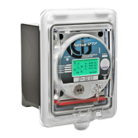
Gives an overview of the Nexus® 1262/1272 legacy Switchboard meter option, highlighting its compact case and easy installation.
Describes the labels on the switchboard meter, noting similarities to socket meters and option-dependent variations.
Details the switchboard meter's specifications and dimensions, noting they are similar to socket meters but with different case sizes.
Guides the user through the installation process for the switchboard meter, emphasizing checking battery connections.
Lists switchboard meter configurations and references wiring diagrams for various forms.
Explains how the E137370 M1 retrofit panel converts an S1 case meter to fit an M1 format cutout.
Lists formulas for calculating power parameters using samples for Wye and Delta services.
Explains how utilities account for energy and peak demand, detailing Block, Rolling, Thermal, and Predictive Window Demand conventions.
Defines Flicker as a visual sensation from illumination intensity changes and its primary effects.
Explains how Flicker is caused by voltage variations and how the signal is processed to model eye-brain response.
Provides a summary of Flicker definitions, including Pinst, Pst, and Plt values, and outlines the measurement procedure.
Guides on setting up Flicker parameters, including frequency, short-term, and long-term test times.
Describes the Flicker Polling screen interface, explaining functions for time, status, frequency, and voltage monitoring.
Explains the meter's capability to log Flicker values independently, including recording various times and values.
Details how Flicker values can be polled through the Communications Port, referring to Modbus and DNP Mapping manuals.
Guides on using the Log Viewer to access, graph, or export logged Flicker data.
Provides performance notes for Flicker measurements, including time synchronization, frequency selection, and data storage.
Discusses calculating Transformer Loss Compensation values manually or via an Excel spreadsheet.
Refers to using the TLC Calculator and spreadsheet copies with example numbers for Transformer Loss Compensation.
Explains terms used in the manual, covering various technical aspects of meter operation and standards.
| Mounting | Panel mount |
|---|---|
| Category | Measuring Instruments |
| Display | Graphical LCD display with backlight |
| Analog Outputs | 4 analog outputs, 0-1 mA, 4-20 mA, or 0-5 VDC |
| Communication Ports | Ethernet, RS-485 |
| Protocols | Modbus RTU, Modbus TCP/IP, DNP 3.0 |
| Accuracy | 0.2% for voltage and current |
| Power Supply | 85-265V AC, 100-300V DC |
| Operating Temperature | -20°C to 70°C |
| Certifications | UL, cUL, CE |
| Power Consumption | Less than 10 watts |