Do you have a question about the Electro-Voice 61PMX and is the answer not in the manual?
Technical specifications for the amplifier's power output capabilities.
Details on the mixer's frequency response across various components.
Specifications regarding the total harmonic distortion levels.
Performance parameters for the integrated power amplifier.
Specifications detailing the noise floor of the mixer section.
Technical details on the equalization capabilities of input channels.
Information on the function and type of channel insert jacks.
Technical parameters for the microphone input stage.
Details on the line input jacks, including impedance and level.
Specifications for the tape input jacks, including impedance.
Technical specifications for the 9-band graphic equalizer.
Lists the maximum voltage gain achievable for different inputs.
Technical data on signal crosstalk between channels and outputs.
Description of the echo effect and its adjustable delay time.
Explanation of the Maximum Power LED indicator's function.
Physical dimensions of the mixer unit in centimeters and inches.
The total weight of the mixer unit in pounds and kilograms.
Information on the electrical power requirements for the mixer.
Details about the construction material of the mixer's case.
Specification for the phantom power voltage supplied to microphones.
Warning against exposing the unit to rain or moisture.
Detailed explanation of the mixer's main input jacks.
Describes the insert jack for adding external signal processing equipment.
Information on the balanced, high-impedance line input jack.
Explanation of the balanced, high-impedance microphone input jack.
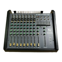
Detailed descriptions of all the mixer's control knobs and sliders.
How to adjust the signal input level using the Gain control.
Explanation of the High and Low EQ controls for tone adjustment.
Adjusts the treble content of the input signal.
Adjusts the bass content of the input signal.
Sets the overall level of the monitor mix.
Adjusts the amount of signal sent to the reverberation unit.
Monitors input channels for clipping or overload conditions.
Adjusts the signal output level to subgroups or main mix.
Controls related to the subgroup section of the mixer.
Input for connecting stereo tape decks.
Output carrying the sum of all main mix input channels.
Output for the monitor mix, excluding main output equalization.
Output for effects and reverberation information.
Input for externally-generated signals from effects devices.
Function of EQ IN, EQ OUT, and POWER AMP IN jacks.
Details on adjusting audio frequencies using the graphic equalizer.
Controls for adjusting reverberation levels and delay.
Adjusts reverb signal to the main channel output.
Adjusts reverb signal to the monitor output.
Controls the interval between echoes in the reverberation signal.
Adjusts the overall volume of the main and monitor output signals.
Descriptions of the Maximum Power, Power, and Phantom Power LEDs.
Indicates when the Power Amp Input exceeds a certain level.
Indicates when the unit is powered on.
Indicates when phantom power is active.
Information on interfacing the amplifier and graphic equalizer.
Description of the connections and controls on the rear panel.
Output jacks for connecting speakers to the power amplifier.
Switches the AC power for the mixer on and off.
Controls the phantom power supply for microphones.
Important safety and operational guidelines to follow before use.
Instructions and considerations for connecting and setting up the mixer.
Explains how to connect speakers to the TO SPEAKERS jacks.
Advice on correctly assembling 1/4" phone plugs for audio connections.
Guidelines on selecting appropriate wire gauges for speaker cables.
Illustrates connecting various audio sources to the mixer's inputs.
Procedure for connecting speaker cables to the mixer's output.
Instructions for plugging a microphone into the Mic 1 input.
How to connect stereo cassette or CD player line out cables.
Connecting an external keyboard to a channel's line in jack.
Recommended settings for gain, EQ, and fader controls during setup.
Guidance on setting Gain and EQ knobs to initial positions.
Instructions for setting channel faders and the main fader.
Steps for connecting power, turning on the unit, and initial sound checks.
Procedure for plugging in the power cord and activating the mixer.
Tips for adjusting volume levels and managing audio feedback.
Procedures for adjusting tape levels, master volume, and using effects.
How to adjust the sound level from a connected tape deck.
Using the main master control to set the overall sound level.
Advice on using the reverberation effect judiciously for optimal sound.
Guidance on using the graphic equalizer to shape the overall sound.
Caution against opening the unit due to hazardous internal voltages.
Steps to diagnose and resolve issues when the mixer does not power on.
Steps to address the mixer shutting down after normal operation.
Steps to diagnose and resolve issues when there is no sound from the amplifier.
Procedure to identify and fix a mixer channel that is not working.
Steps to diagnose and resolve issues causing high hum or noise levels.
Instructions for cleaning noisy slider controls using contact cleaner.
Guidance on cleaning the mixer's case and control panel.
Step-by-step instructions for reconfiguring the power transformer's primary wiring.
Contact details and information for obtaining factory technical support.
Wiring diagram for setting the unit to operate at 100 volts AC.
Wiring diagram for setting the unit to operate at 120 volts AC.
Wiring diagram for setting the unit to operate at 200 volts AC.
Wiring diagram for setting the unit to operate at 220 volts AC.
Wiring diagram for setting the unit to operate at 240 volts AC.
| Channels | 6 |
|---|---|
| Input Channels | 6 |
| Phantom Power | +48V |
| Equalizer | 3-band EQ on each channel |
| Effects | Reverb |