75
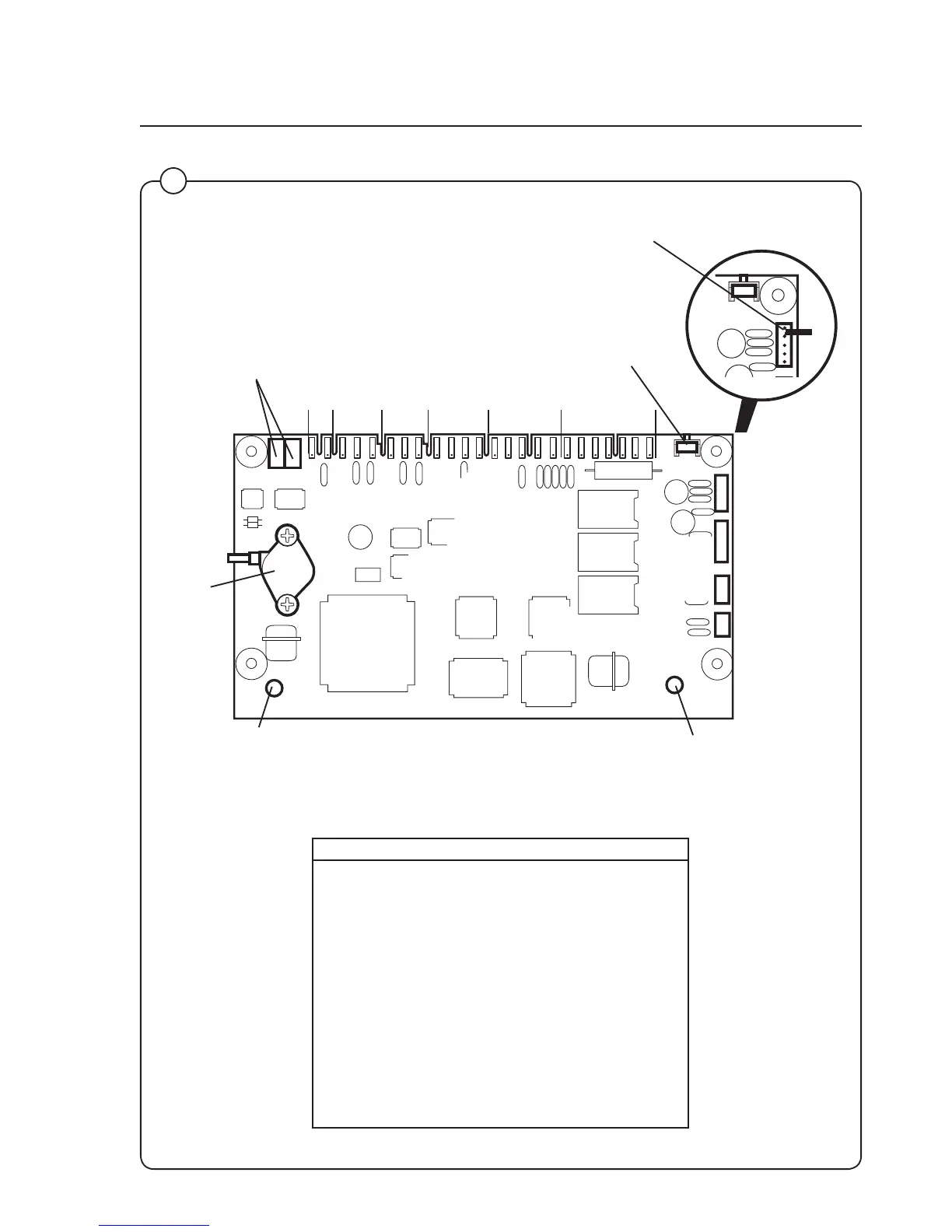
Programme unit
3972
2
X7
X1 X2 X3 X4 X5 X6
X7
X8
X9
X10
Red LED:
Continuous red light = voltage
supply OK
Green LED:
Quick blinks = communication
between CPU card and I/O card.
(Not for FOM71 CLS).
Pushbutton SW1: used as an acknow-
ledgement button when in the Service
programme mode (the same function
is also available on the communica-
tion card).
The two pins in switch X7 are shorted to confirm
changes made in Configuration 1 and 2.
Card Switch Function
X1 Input from water temperature sensor
X2 not used
X3 not used
X4 Output to motor controller
X5: 1-3 Serial communication with I/O card 1
X5: 4-5 Voltage supply from I/O card 1
X6: 1-5 Serial communication with display card
X6: 6-7 Voltage supply to display card
X7 PC communication
X8 Motor communication (reserved)
X9 Scale communication
X10 Internal communication (not used)
Pressure
sensor
2 1 3 2 1 3 2 1 4 3 2 1 5 4 3 2 1 7 6 5 4 3 2 1
P1, P2 Used for factory
calibration of the pres-
sure sensor.