14. PAL MATRIX ADJUSTMENT
(a) Tune in a color bar signal.
(b) Use oscilloscope with 2 channels input and set to the " X-Y ' mode.
(c) Channel 1 ( X ) connected to TP28 ( Pin 1 of IC1401 ) ( R-Y ).
(d) Channel 2 (Y) connected to TP29 (Pin 3 of IC1401) (B-Y).
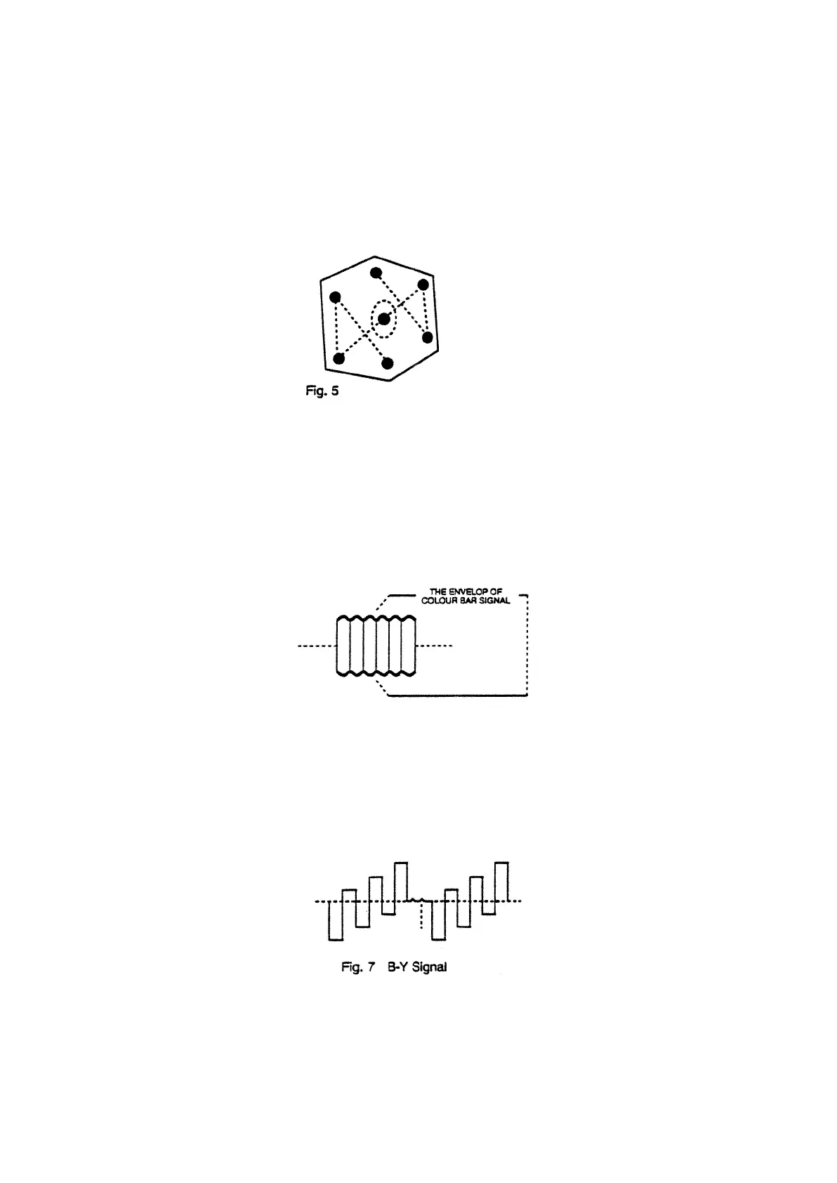
(e) Adjust amplitude balance VR202 until the center points of the two waveforms coincided (as shown in Fig. 5).
(f) Adjust L203 and 1204 until all other points of the two waveforms coincided (as shown in Fig. 5).
15. COLOR DECODER ADJUSTMENT FOR SECAM SYSTEM
A. IDENT FILTER ADJUSTMENT
(a) Apply a SECAM color bar signal ( 60dB level ) to the input
(b) Connect a high impedance DC voltmeter to TP31 ( Pin 10 of IC1401 ).
(c) Adjust L210 of the ident filter for minimum voltage at Pin 10 ( 3V ).
B. BELL FILTER ADJUSTMENT
(a) Apply a SECAM color bar signal ( 60dB level ) to the antenna input.
(b) Connect an oscilloscope to TP30 ( Pin t4 of IC1401 ).
(c) Adjust L206 to make the envelop of color bar signal into flat response ( Fig. 6 ).
Fig. 6 SECAM Color Bar Signal
C. B-Y DEMODULATION
(a) Apply a SECAM color bar signal to the input.
(b) Connect an oscilloscope to TP17 ( Pin 3 of IC1401 ).
(c) Adjust L209 to obtain a B-Y signal will, correct chrominance output ( Fig. 7 )