-3-
(Part designs are subject to change without notice).
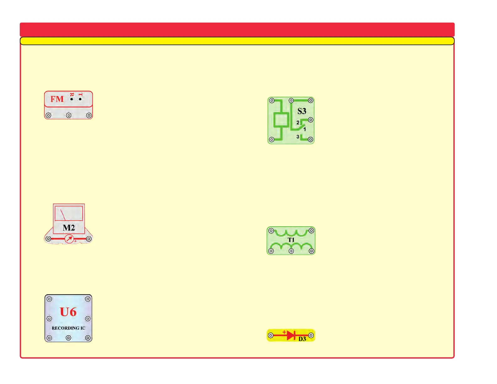
The FM module (FM) contains an integrated FM radio circuit.
Ref
er to the figure below for the pinout description:
The meter (M2) is a very important indicating and measuring
de
vice. You’ll use it to measure the amount of current or voltage
depending on the circuit configuration. Notice the meter has a “+”
sign, indicating the positive terminal (+ power from the batteries).
The other snap is the negative terminal (– power return to
batteries). The meter has a switch to change between scales,
indicated as LOW and HIGH (or 10mA and 1A).
The recording IC module (U6) contains an integrated recording
circuit.
You can record a message up to five seconds long. There
are also three pre-recorded songs. Refer to the figure below for the
pinout descriptions:
The relay (S3) is an electronic switch with contacts that can be
closed or opened.
It contains a coil that generates a magnetic field
when current flows through it. The magnetic field attracts an iron
armature, which switches the contacts (see figure).
The transformer (T1) consists of two coil windings on one core.
One coil is called the Pr
imary (input) and the other the Secondary
(output). The purpose of the transformer is to increase the amount
of AC voltage applied to the primary. This transformer is a step-up
transformer.
Diode (D3) - Think of a diode as a one-way valve that permits
current flo
w in the direction of the arrow. The anode (arrow) is the
positive side, and the cathode (bar) is the negative. The diode
conducts or turns on when the voltage at the anode is 0.7V or
greater.
MORE
About Your New Snap Circuits
®
Parts (Note: There is additional information in your other project manuals).
(+)
OUT(–)
FM Module:
(+) - power from batteries
(–) - power return to batteries
T - tune up
R - reset
OUT - output connection
See project #307 for example of
proper connections.
(+)
OUT
(–)
Recording IC Module:
(+) - power from batteries
(–) - power return to batteries
RC - record
Play - play
OUT - output connection
Mic + - microphone input
Mic – - microphone input
See project #308 for example of
proper connections.
RCPlay
Mic –
Mic +
COM
Relay:
Coil - connection to coil
Coil - connection to coil
NC - normally closed contact
NO - normally open contact
COM - Common
See project #341 for example of
proper connections.
Coil
Coil
NO
NC
B
CTB
Transformer:
A - less windings side
A - less windings side
B - more windings side
B - more windings side
CT - center tap
See project #347 for example of
proper connections.
A
A
Anode
Diode:
Anode - (+)
Cathode - (–)
Cathode
(+)
(–)
Meter:
(+) - power from batteries
(–) - power return to batteries
Less Windings
More Windings
Our Student Guides give much more information about your parts, along with a complete lesson in basic electronics. See www.snapcircuits.net/learn.htm or page 62 for more information.
 Loading...