About Your Snap Circuits
®
Parts
ELECTRONICMODULESCOLORLED
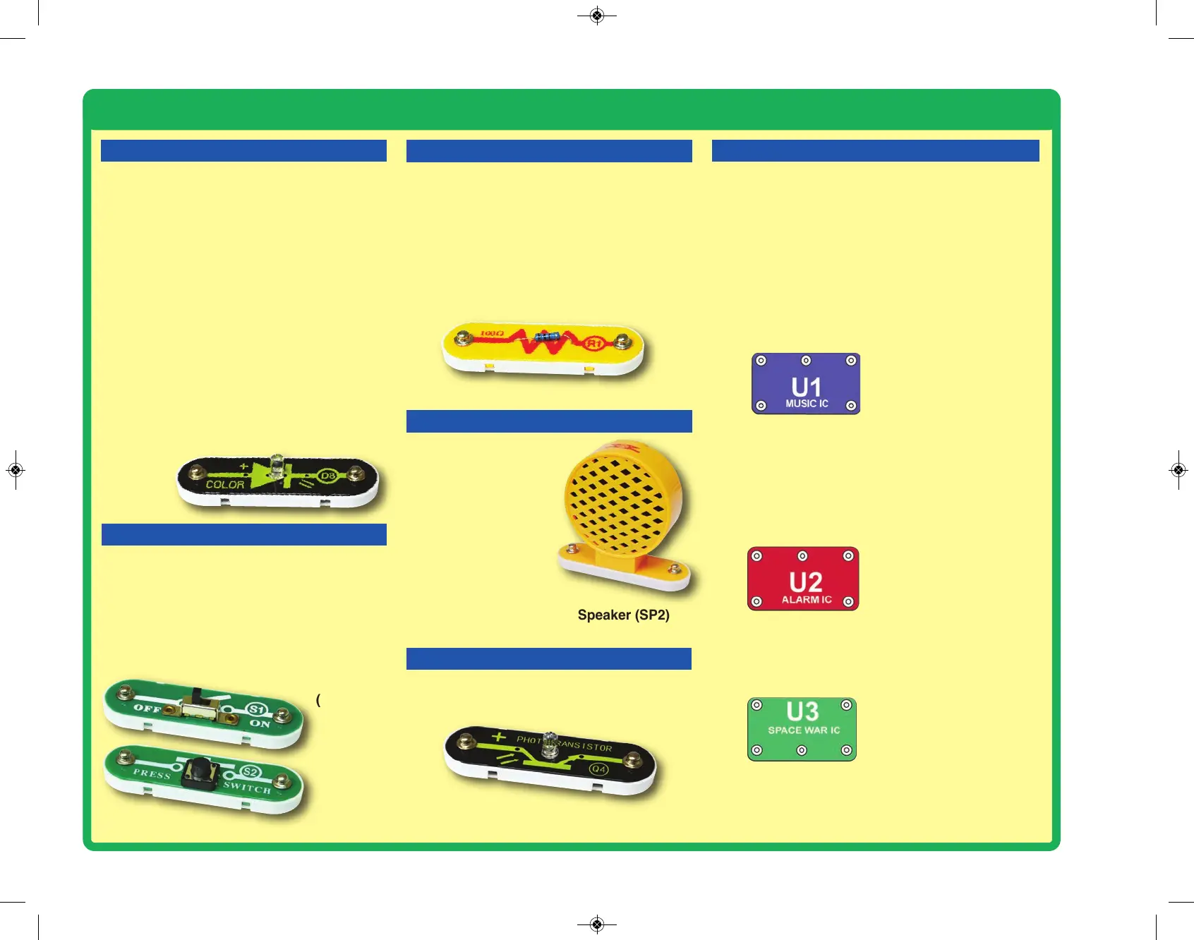
The color LED(D8) is a light emitting diode,
and may be thought of as a special one-way
light bulb. In the “forward” direction, (indicated
by the “arrow” in the symbol) electricity flows
if the voltage exceeds a turn-on threshold
(about 1.5V for red, about 2.0V for green, and
about 3.0V for blue); brightness then
increases. The color LED contains red, green,
and blue LEDs, with a micro-circuit controlling
then. A high current will burn out an LED, so
the current must be limited by other
components in the circuit (though your Snap
Circuits
®
LEDs have internal resistors to
protect against incorrect wiring). LEDs block
electricity in the “reverse” direction.
RESISTORS
100
W
Resistor (R1)
Resistors “resist” the flow of electricity and are
used to control or limit the current in a circuit.
Snap Circuits
®
Select includes a 100W
resistor (R1). Materials like metal have very
low resistance (<1W), while materials like
paper, plastic, and air have near-infinite
resistance. Increasing circuit resistance
reduces the flow of electricity.
Slide &Press
Switches
(S1 & S2)
PHOTOTRANSISTOR
The phototransistor (Q4) is a component
that uses light to control electric current.
Phototransistor (Q4)
SLIDE&PRESS SWITCHES
The slide & press switches (S1 &S2) connect
(pressed or “ON”) or disconnect (not pressed or
“OFF”) the wires in a circuit. When ON they have
no effect on circuit performance. Switches turn on
electricity just like a faucet turns on water from a
pipe.
(+)
HLD
OUT
(–)
TRG
IN1
(–)
IN2
IN3
OUT
IN1
(+)
OUT
IN2
(–)
Music IC:
(+) - power from batteries
(–) - power return to batteries
OUT - output connection
HLD - hold control input
TRG - trigger control input
Music for a few seconds on
power-up, then hold HLD to (+)
power or touch TRG to (+)
power to resume music.
Alarm IC:
IN1, IN2, IN3 - control inputs
(–) - power return to batteries
OUT - output connection
Connect control inputs to (+)
power to make five alarm
sounds, see project 13 for
configurations.
Space War IC:
(+) - power from batteries
(–) - power return to batteries
OUT - output connection
IN1, IN2 - control inputs
Connect each control input to
(–) power to sequence through
8 sounds.
The music, alarm, and space war ICs (U1, U2, and
U3) contain specialized sound-generation ICs and
other supporting components (resistors, capacitors,
and transistors) that are always needed with them.
This was done to simplify the connections you need
to make to use them. Schematics for them are
available at www.snapcircuits.net/faq.
The speaker (SP2)
converts electricity into
sound by making
mechanical vibrations.
These vibrations
create variations in air
pressure, which travel
across the room. You
“hear” sound when
your ears feel these air
pressure variations.
SPEAKER
Speaker (SP2)
Color LED
(D8)
-5-
 Loading...