3
4
5
6
FIG.1
7
APPLIANCES SHALL BE INSTALLED JUST BY DULY QUALIFIED PERSONS.
No appliance of this range weighs more than 20 kg, so that one-person alone can move them. For the weight of each item, please
see Table 1.
While moving or installing the appliance, you shall wear gloves or similar protection means in order to prevent accidents for your
own and third persons’ safety.
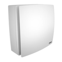
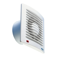
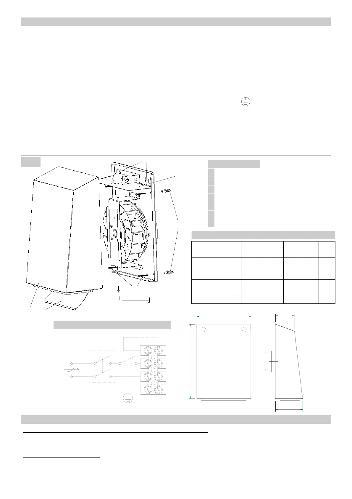
Install your appliance according with Fig.1.
Fasten your appliance steadily by means of the supplied wall plugs.
Make reference to Fig 2 for the connection of the appliance.
Connection to the mains supply has to be done by means of a recessed wire.
Provide proper electric protections according to the installed model.
AS APPLIANCES ARE SHEET-MANUFACTURED (Class I), IT IS ABSOLUTELY IMPERATIVE THAT THEY ARE CON-
NECTED TO THE GROUND SYSTEM OR COLLECTOR ON THE INSTALLATION SPOT.
When all the electric connection are carried out, check the connection terminals for their correct locking, close the external sheet
case and start the appliance.
After the appliance has started, check whether:
- the rotation direction is correct.
- the electric absorption corresponds to the rating.
- excessive vibrations can compromise the appliance stability.
Should the appliance be connected through a regulator, make sure that said regulator is proportionate to the power of the con-
cerning appliance.
MODE OF INSTALLATION
MAINTENANCE AND CLEANING
The appliance maintenance shall be carried out just by qualified persons.
The motor and the fan wheel shall be periodically controlled, according to the handled fluid and with the operation type; afterwards
every six months of continuous operation.
Before any maintenance or cleaning operation, switch off the appliance by opening the master switch or the specific
safety switch of the appliance.
During the normal cleaning operations, check the integrity of all appliance parts.
LEGEND FIG. 1
FLAP
2
WALL FIXING SCREWS
3
CASE FIXING SCREWS
4
WALL PLUG
5
ELECTRICAL CONNECTION SUPPORT
6
1
SHEET METAL CASE
1
2
MODEL A B
Ød
(mm)
C D Kg
EXT 100A
EXT 100B
EXT 150A
EXT 160A
260 355
98
98
148
157
92 131 4,40
EXT 150B
EXT 160B
EXT 200A
360 440
148
157
198
92 131 7,30
EXT 200B
360 440 198 92 131 7,90
Ta
(°C)
50
60
60
60
60
60
60
70
TAB. 1
CABLE ENTRY HOLE
7
CONNECTION FIG. 2
Maico Italia S.p.A. - Via Maestri del Lavoro, 12 - 25017 Lonato del Garda (BS) - ITALY
Tel. +39 0309913575 Fax +39 0309913766 e-mail: info@maico-italia.it www.maico-italia.it
A
C
D
B
O
N
L
 Loading...