3
2
must discharge directly outside the building.
WARNING: Damage can be caused to the device if the following instructions
are not applied!
•Donotusetheproductatenvironmentaltemperaturesmorethan40°C.
•Donotleavetheapplianceexposedtoatmosphericagents(rain,sun,snow,etc.).The
possible applications of this product are illustrated in this manual.
•Donotimmersetheapplianceorpartsofitinwateroranyotherliquids.
•When cleaning or carrying out ordinary maintenance, check the integrity of the appli-
ance.
•Theowofairorfumesthatisconveyedbytheappliancemustbecleanandfreeofgreasy
elements,soot,chemical/corrosiveagentsandinammableorexplosivemixtures.
•Donotobstructtheairinletandoutletoftheapplianceinanywaywhatsoever.Whenus�Donotobstructtheairinletandoutletoftheapplianceinanywaywhatsoever.Whenus-
ingairductingmakesurethattheductingisnotblocked.
Itisrecommendedtoinstallitataminimumheightof2.30metresfromtheoor.•
•For an optimum functioning of the appliance, it is necessary to ensure an adequate re-
circulation of air in the room. Consult the local norms with regards to this.
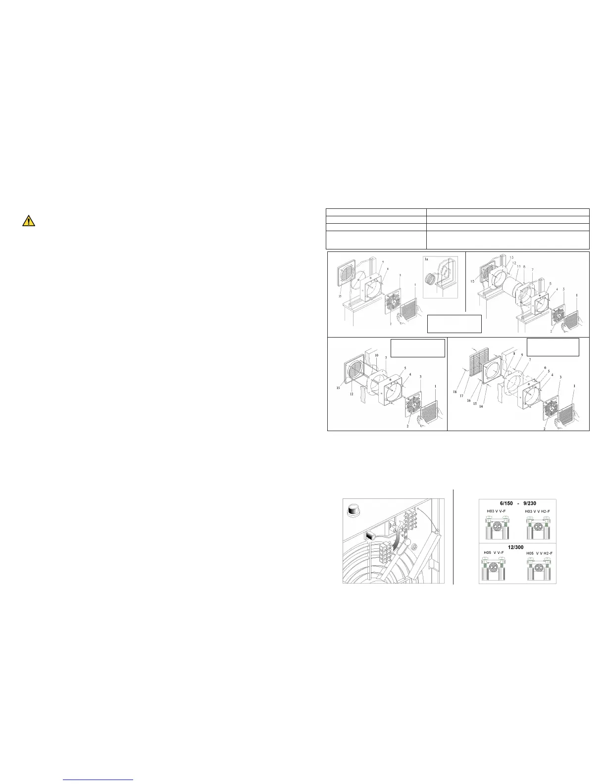
INSTALLATION
PLEASE REFER TO THE NUMBERING INDICATED IN INCREASING ORDER (NOT ADJOINING), TO DISMANTLE THE
FAN.
Installation in single glazed window (Fig. 1): dismantle the fan into its various components as shown and reassemble it on the
window as shown in Fig. 1.
Installation into double glazed windows (Fig. 1 and Fig. 1A): refer to Fig. 1 for dismantling and reassembling the fan. If neces-
saryusethedouble�glazingkit,insertingtheringsasshowninFig.1A.
Installation into double windows (Fig. 2): dismantleandreassemblethefanasshowninFig.2usingthedoublewindowkit.
Installation into walls (Fig. 3 and Fig. 4): wall installation can be carried out using two different methods:
�byusingwallrodsinthoseinstanceswherethereisnodirectaccesstotheoutside(Fig.3).
�byusingwallplugsifthereiseasyaccesstotheoutside(Fig.4).
See Fig. 5 for all electrical connections.
See Fig. 5n for information on dismantling the terminal block in models 9/230 and 12/300.
OPERATION
Manual version: pulling the cord opens the shutters and the fan operates. Pulling the cord a second time closes the shutters and
stops the fan.
Automatic version: thefanisoperatedbythecontrolswitch.Aneonlightonthefanshowsthatthefanisoperating.Theshutters
onthesefansareofthedelayedactiontypeandwilltakeseveralsecondsbothtoopenandclose.
Somemodelsareprovidedwithaspeedcontroller.Whenthespeedcontrollerissetat“0”theshuttersonthefanwillstayopen
eventhoughthemotorisnotoperating(theneonlightison).
MAINTENANCE AND CLEANING
Before carrying out any maintenance or cleaning operations, disconnect the mains electrical supply.
Remove the front cover with reference to the type of installation carried out.•
Clean the front cover with water or a mild detergent.•
Disconnectthefanfromthesupplycable,beforedismantlingthemotorholderfromthebody(formodels9/230and12/300•
only).
The motor-fan assembly should be cleaned only with a dry brush or dry cloth.•
During cleaning operations, ensure that the motor-fan assembly does not come into contact with any type of liquid or solvent. •
Ifthisshouldoccur,contactaqualiedtechnicianbeforereassemblingthefan.
PROBLEM CAUSE AND REMEDY
The appliance does not switch on There is no voltage. Checkthemainswitchand/ortheelectricalconnections.
The impeller does not turn Checkthatitsmovementisnotsloweddown.
Automaticmodels:if the shuttersremainopen
and the neon light is on, but the motor is not
running
Whereaspeedcontrollerisusedchecktoseethatitisnotsetat“0”.
LEGEND FIG. 1-2-3-4
Front1.
Plate disassembly screws2.
Motor-holder plate3.
Bushes(sleeves)4.
Intermediate body5.
Wall�xingscrews6.
Flange7.
Flangexingscrews8.
Wallplugs9.
Wallrods10.
Shell11.
Bushes(sleeves)12.
Flange13.
Wallplugs14.
Grille holder15.
Wall�xingscrews16.
External grille 17.
Grillexingscrews18.
5n
6
6/150 Ø = 184 ÷ 188
9/230 Ø = 254 ÷ 258
12/300 Ø = 324 ÷ 329
1
3
2
4
6/150 Ø = 184 ÷ 188
9/230 Ø = 254 ÷ 258
12/300 Ø = 324 ÷ 329
6/150 Ø = 165 ÷ 170
9/230 Ø = 240 ÷ 245
12/300 Ø = 295 ÷ 300
TROUBLE SHOOTING
 Loading...