Page 21000004299 (Rev. B - 04/2018)
LVRC8WS_2AWR, LVRCWS_2AWR
Installation
For correct and safe installation, please read these instructions completely.
• All Installation work must be performed by an authorized service personnel.
• Disconnect electrical supply serving the Installation area to reduce risk of electrocution.
• Unit not suitable for installations where water jets could be used.
DANGER
WARNING
• Shut off water supply serving the Installation area to reduce risk of water damage.
• Ensure proper ventilation by maintaining clearance from cabinet louvers to wall on each side of Cooler as specied in Rough-In.
• Never wire compressor directly to electrical supply.
• Thoroughly ush all water lines and ttings of all foreign matter before connecting to Cooler.
• Warranty is void if Installation is not made in accordance with current Manufacturing instructions.
CAUTION
• Hose-sets are not to be used for connecting to water mains.
• If inlet pressure is above 100 psig (0.69 MPa), a pressure regulator must be installed in water supply line. Any damage caused by reason of
connecting this product to water supply line pressure outside it’s rated pressure, is not covered by warranty.
• Tools/Items required but not provided:
Installation: Cooler Mounting
1. Remove wall mounting plate(s) from Cooler. Install Wall Mounting Plate(s) as per Rough-In.
NOTE: Mounting plate(s) MUST be supported securely. Add xture support carrier if wall will not provide adequate support.
2. Install water cooler onto wall bracket and secure to wall.
Installation: Water Line connection
1. Ensure Mains Water Supply has Water Shut-off Valve with 3/8” (9.5mm) compression outlet.
2. Connect loose end of supplied 3/8” (9.5mm) unplated copper tube to Water Shut-off Valve. Other end of tube should be connected to inlet of
Filter head. If not connected, simply insert into inlet tting on Filter head until positive stop – approximately ¾” (19mm).Then tighten locknut
handtight to seal.
NOTE: If 3/8” (9.5mm) copper tube must be cut for proper t, remove all burrs from the outside of tube and re-ush before use.
3. Install waste trap. Remove the slip nut and gasket from the waste trap and install them on the cooler waste line making sure that the end of
the waste line ts into the waste trap. Assemble the slip nut and gasket to the waste trap and tighten securely.
4. It is recommended that the drain trap be insulated to avoid excessive condensation due to chilled water running through the trap.
5. Turn on building water supply and open Water Shut-off Valve. Check all connections for leaks and correct any found.
Installation: Electrical connection
1. Rotate fan to insure proper clearance and free fan action.
2. Connect modular (C-13) end of International Power Cord Set (sold separately) into Power Inlet on Cooler and ensure plug-end reaches
electrical outlet. Do not plug into electrical outlet!
• Center Punch
• ½” Socket & Ratchet Wrench
• 5/32” (4mm) Allen Wrench
• Fasteners for wall type
• Water Shut-off Valve with 3/8” (9.5mm) Compression outlet.
• Waste Trap (non-metallic)
• Safety Glasses
• Protective Gloves
• Electric Drill
• ¾” (19mm) Wrench or Crescent Wrench
• Utility Knife
• Tape Measure
• Pencil
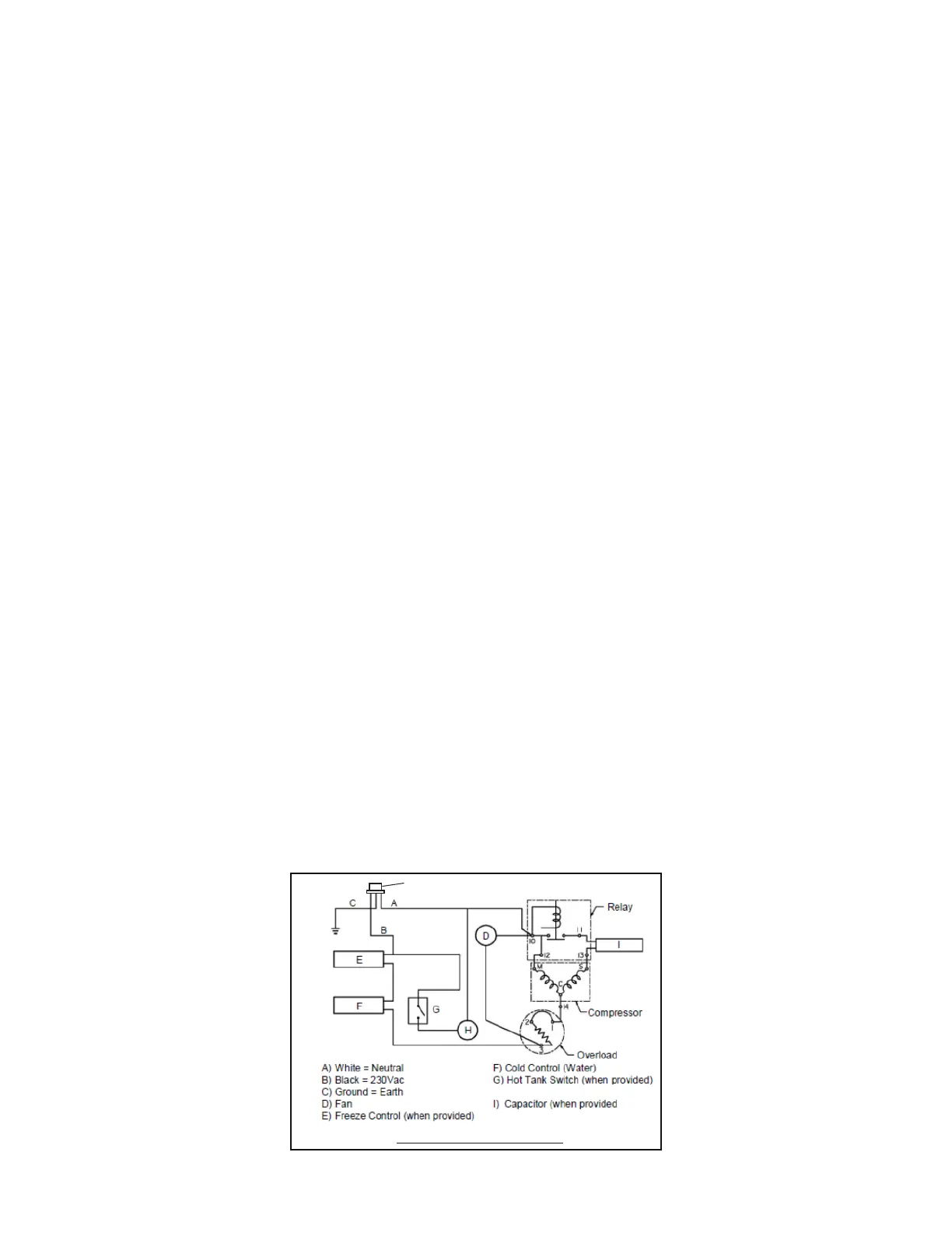
220Vac, 50Hz Wiring Diagram
H
H) Power Inlet
 Loading...