1 Appropriate use
Models 363 098, 363 V98, 363 V99, 364 097, 462 009 R
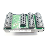
The interface serves to link several elobau sensors with one elobau control unit.
Model 363 R98
The interface serves to link several elobau locks with one elobau control unit.
Safety/Dangers
- Ensure that interface is only installed and put into operation by specially-trained authorised personnel.
- Only operate the interface when it is in an undamaged condition.
- Ensure that interface is only used for protection against dangers.
- Ensure that all safety requirements applying for the machine in question are observed.
- Ensure that all applicable European directives and national laws/directives are observed.
2Function
Model 363 098
The interface links up to 4 sensors with contact makers and contact breakers.
If more than 4 sensors are connected:
- Connect additional interface units in parallel.
The respective LED lights up, if a connected sensor is de-energized.
Model 363 R98
The interface connects up to three interlocks.
- Only to be used in conjunction with elobau sensors 118 HVE 01.
If less than 3 interlocks are connected:
- The contact maker and the pin contacts must be bridged.
The first LED lights up when the pin of a connected interlock has engaged.
The second LED lights up when the pins of two connected interlocks are engaged.
The third LED lights up when the pins of all connected interlocks are engaged.
Models 363 V98 and 363 V99
The interface links up to 8 sensors with contact makers.
- To be used only in conjunction with elobau sensors that have V62 as the 4th, 5th and 6th digits (see
Type denomination/Variants of the sensor instructions).
If less than 8 sensors are connected:
- Bridge unassigned connections before the last sensor.
- Connect returns of last sensor to clamps 30 and 32.
Model 364 097
The interface links up to 4 sensors with contact makers.
- To be used only in conjunction with elobau sensors that have 262 as the 4th, 5th and 6th digits (see
Type denomination/Variants of the sensor instructions).
If less than 4 sensors are connected:
- Bridge unassigned terminals of contact maker chain.
The respective LED lights up when a connected sensor is energized.
Model 462 099 R
Up to a maximum of 4 sensors having contact breakers and contact makers can be connected to this
interface unit.
The control output is activated and the respective LED is illuminated when the respective sensor is de-
energized.
LED displays
Model 363 098
Model 363 R98
Model 364 097
Model 462 099 R
Control units
The following control units can be connected:
3Installation
- Snap the interface onto a mounting rail (DIN 50 022) in the switch cabinet.
The interface is fixed.
- Connect interface, see Technical Data.
4 Putting into operation
The interface is activated when a connected sensor is energized.
5 Troubleshooting
If the interface shows any fault:
- Replace interface.
EC Declaration of conformity
We declare that the interfaces 363 098, 363 R98, 363 V98, 363 V99, 364 097 and 462 099 R
fulfil the conformity to the following guidelines:
98/37/EC, 2006/95/EC, 2004/108/EC
Related harmonized standards:
DIN EN 60204-1, DIN EN 61000-6-2, DIN EN 61000-6-4, DIN EN 954-1
LED Meaning when LED is lit
S1 Sensor 1 de-energized
S2 Sensor 2 de-energized
S3 Sensor 3 de-energized
S4 Sensor 4 de-energized
LED Meaning when LED is lit
H1 Interlock 1, pin locked
H2 Interlock 2, pin locked
H3 Interlock 3, pin locked
LED Meaning when LED is lit
H1 Sensor 1 energized
H2 Sensor 2 energized
H3 Sensor 3 energized
H4 Sensor 4 energized
LED at terminal Meaning when LED is lit
7 Sensor 1 de-energized
11 Sensor 2 de-energized
16 Sensor 3 de-energized
20 Sensor 4 de-energized
GB
Type denomination Control unit
363 098
462 099 R
462 12. G1.
462 121 E1.
462 121 H1.
463 12. ..
363 R98 462 M21 H31 01
363 V98
364 097
462 M41 H3.
462 M51 H.1
471 M41 H31
363 V99 462 111 B1
462 114 B1
470 111 B1
470 115 B1
Danger
Danger of electrocution!
Ensure that interface is only installed and put into operation by specially-trained
authorised personnel.
Danger
Danger of electrocution!
Ensure that interface is only installed and put into operation by specially-trained
authorised personnel.
Leutkirch, 12 June 2008 Factory:
Zeppelinstraße 44
88299 Leutkirch
Germany
Tel.: +49 7561 970-0
Fax: +49 7561 970-100
E-mail: info@elobau.de
Web: www.elobau.com
Michael Hetzer,
General Manager
elobau
Elektrobauelemente GmbH & Co. KG
Postfach 1265
88306 Isny/Allgäu
Germany
 Loading...