Application and Operation
Flow Meter components:
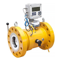
The Signal Processing Unit (SPU) – houses the flow meter
electronics.
Two Ultrasonic Transducers per flow measurement path.
The spoolpiece (Flow Cell) designed for gas flow measurement.
An optional Pressure Sensor.
An optional Temperature Sensor.
p
m
(or p
r
) Pressure Connection (for flow pressure); one or two
(provided with adapter piece).
The SPU Label (see subsequent sections)
The Main Type Plate
The ultrasonic flow meter is to be operated on the local display or by “remote
control”, for example, by means of a PC with the SonicExplorer software, as
part of your specific flow meter.
The ultrasonic flow meter is intended for flow measurement as
indicated on the SPU label and the flow meter (main) type plate.
Never exceed any limitations for use!
This document provides essential details for safe installation and
maintenance of the ultrasonic flow meter, including a non-
exhaustive list of safety prescriptions provided in Annex C –
Safety Prescriptions (p. 33).
It is also required to read and understand all other documentation
of your flow meter; please see the reference list Appendix I –
References at the back of this manual. Alternatively, most
documents are available online at http://www.docuthek.com/.
 Loading...