14 SBC session border controllers
16 x RJ-48 connectors for E1 streams
1
2 x RJ-45 ports for connection of external synchronization sources
1
Device operation indicator
Sync.1 external synchronization interface operation indicator
1
Sync.2 external synchronization interface operation indicator
1
Device aux power indicator
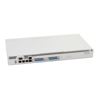
The rear panel of the device is shown in Figure 7.
Figure 7 — The rear panel of SBC-2000 (based on SMG-2016)
The Table below lists rear panel connectors of the device.
Table 5 — Description of rear panel connectors of the switch
Modules with connector for power supply
Removable ventilation modules with hot-swapping
Earth bonding point of the device
Not used for configuration SBC-2000
 Loading...