INTRODUCTION
The CMeX50 is a wireless M-Bus Receiver handling up to 800 wireless
M-Bus meters and up to 32 wired M-Bus meters. The product can
operate in all commonly used wireless M-Bus modes: T1, C1 and S1.
For a complete description of the product or for information in other
languages, visit the Elvaco AB website, www.elvaco.com.
OVERVIEW
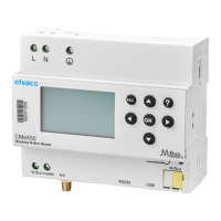
1. Serial number
2. Display
3. M-Bus master
4. Antenna connector
5. RS232 connector
6. DIN-rail lock
INCLUDED ACCESSORIES
The CMeX50 is delivered with a magnetic mount antenna, an USB cable
and an RS232 cable.
MOUNTING
The product should be mounted on a DIN-rail. The DIN-lock (6) on the
bottom is used to mount and demount the unit from the DIN-rail. To
fully comply with safety regulations, a DIN-rail enclosure must cover the
terminals.
POWER SUPPLY
The installation should be performed by a qualied electrician or an
installer with the required knowledge. The power supply should be
connected via a clearly marked, easily accessible and close switch so the
unit can be switched o during service work. The main supply should be
connected to screw terminal (9) and screw terminal (10). Main supply
voltage should be in the range of 100-240 VAC, 50/60 Hz. Connect
protective earthing to screw terminal (11).
M-BUS MASTER
The CMeX50 will store the connected wireless M-Bus meters and they
will be readable using standard M-Bus commands. Except from handling
wireless M-Bus slaves, the CMeX50 has an integrated M-Bus Master
which can drive up to 32 wired meters. M-Bus is a multi-drop 2-wire
bus with no polarity. Use a cable of area 0.25-1.5 mm
2
, e.g. a standard
telephone cable (EKKX 2x2x0.5). Connect the wiring to the connector
(3). Do not exceed the maximum cable length of 1000 m.
IMPORTANT
The product handles up to 32 wired M-Bus meters. Overloading the bus
will show an error message on the display and turn o the M-Bus bus.
All connected M-Bus slave devices must have unique primary or
secondary M-Bus addresses depending on addressing mode.
ANTENNA
Mount the antenna in a suitable place. Connect the cable to the SMA
connector (4). If the included antenna’s range is inadequate, please
contact Elvaco for more information about antenna options.
IMPORTANT
• CMeX50 should be connected to the antenna after the antenna
wiring is done. Otherwise the SMA connector can be damaged!
• Do not mount the antenna close to any metallic objects.
• Do not mount the antenna close to the M-Bus 2-wire bus.
• Do not mount the antenna inside a metallic cabinet.
M-BUS SLAVE PORTS
The product is equipped with four dierent M-Bus slave ports (IR
interface left, RS232 (5), USB (7) and M-Bus slave interface (8)) to
enable wide integration. These ports can be used to:
• Read the connected wireless M-Bus slaves as normal M-Bus slaves
• Read the connected wired M-Bus slaves (transparent)
Slaves can be read using primary and/or secondary addressing. The
CMeX50 itself is available as an M-Bus slave with the secondary address
equal to the serial number.
RS232 interface
The RS232 interface is used as a standard transparent M-Bus interface
over RS232. Use the included RS232 cable (RJ45 to D-SUB9) and
connect to any standard RS232 D-SUB9 connector.
USB interface
The USB interface is used as a standard transparent M-Bus interface
over USB. Use the included USB cable and connect to any standard
USB master port. When using Microsoft Windows® operating systems,
a virtual comport will automatically be generated when connecting the
product to the computer. Additional USB drivers can be downloaded
from the Elvaco web site: www.elvaco.com.
M-Bus 2-wire interface
The M-Bus 2-wire interface acts like any other M-Bus slave device on
the 2-wire bus. The nominal current is 1T (1.5 mA). This interface can be
directly used with any standard M-Bus master.
IR interface
The IR interface is used as a standard transparent M-Bus interface over
IR. This port can be used together with M-Bus master products from
Elvaco, i.e. CMe2100 and CMe3000. In this way it is possible to extend
the product with TCP/IP and GPRS communication.
7. USB connector
8. M-Bus slave
9. Power supply L
10. Power supply N
11. Protective earthing
12. Keypad
13. IR interface right
CMeX50
Wireless M-Bus Receiver