17
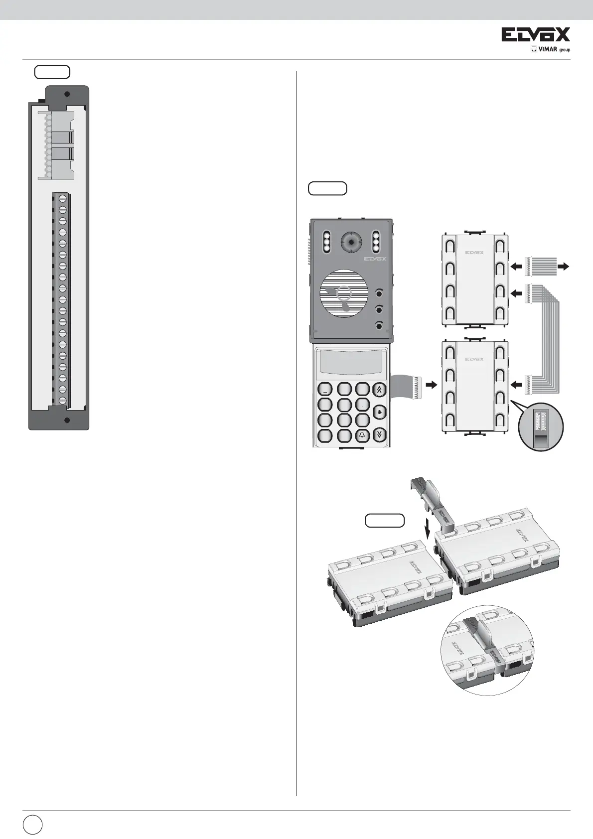
Fig. 2
V13458V1M1V2SR+ICHVL4F1F2+L 6
CN1
ELVOX CS2375 211004
M
V13458V1M1V2SR+ICHVL4F1F2+L 6 M
TERMINAL BLOCK
Terminal Description
+I Monitor shutdown control terminal.
S
Electric lock activation control terminal.
F2 Auxiliary function 2 activation control ter-
minal.
F1 Auxiliary function 1 activation control ter-
minal.
+L Panel active terminal.
CH Call signal activation control terminal.
8 Terminal for voice signal in building
complex.
6 Terminal for digital signal in building
complex.
V2 Video signal terminal.
M Video signal earth terminal.
V1 Video signal input terminal.
5 +13.5Vdc supply voltage terminal.
4 Negative supply voltage terminal.
3 Terminal for voice signal to interphone/
monitor cable riser.
1 Terminal for digital signal to interphone/
monitor cable riser.
V Video signal output terminal.
M Video signal earth terminal.
VL Key lighting LED power supply terminal
for additional modules.
PRELIMINARY OPERATIONS
(only for versions 1282/P and 1286/P)
Electronic units type 1282/P and type 1286/P can be connected to indivi-
dual push-button modules to provide up to a maximum of 31 push-buttons
using the additional modules with push-buttons in single row, or up to 30
push-buttons using an additional module with push-buttons in double row.
For expansion with call push-buttons it is necessary to connect additional
modules (type 12TS or 12TD): 12TS for push-buttons in single row or type
12TD for push-buttons in double row.
Fig. 28
Back
Fig. 29
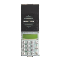
Type 1282/P, type 1286/P
3
2
1
1 2 3
4
5
6
7 8 9
0
ABC DEF
GHI
JKL
MNO
PQRS
TUV
WXYZ
+
R
EN
 Loading...