VARIATION 13
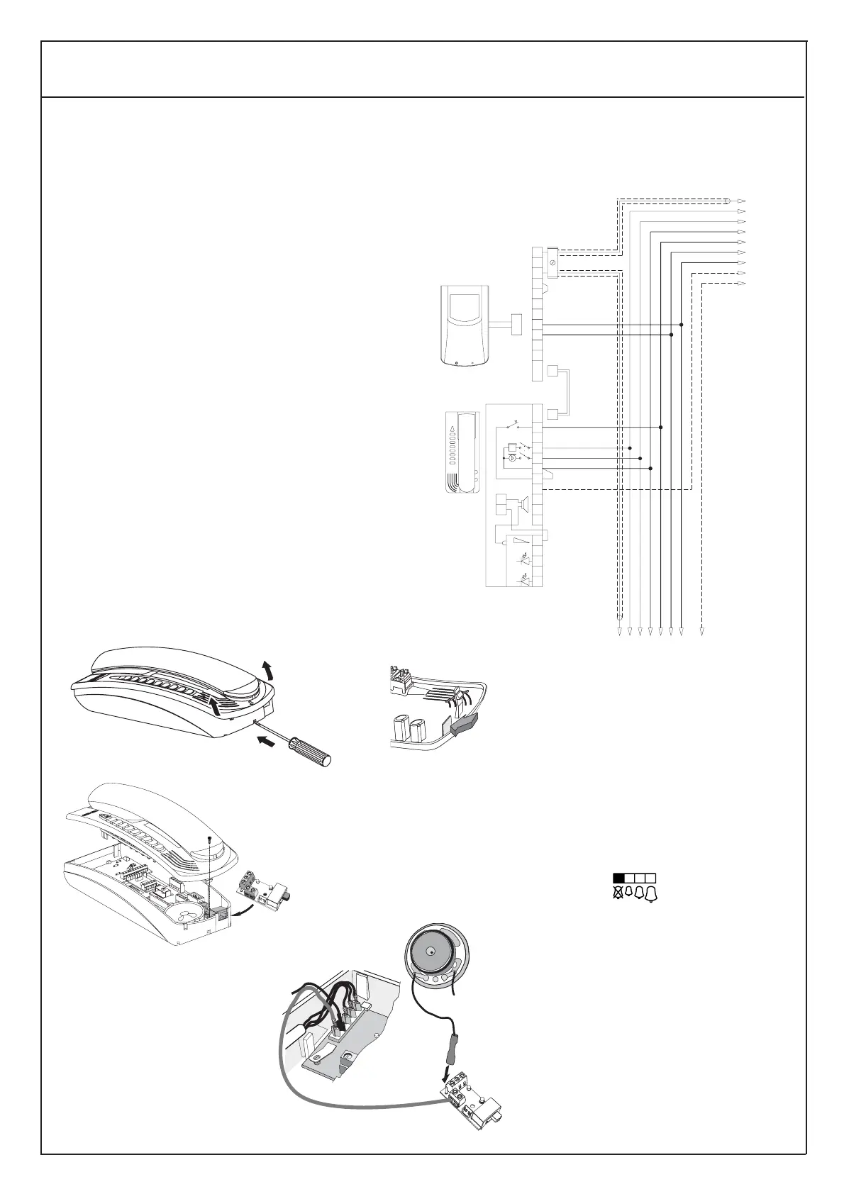
Wiring diagram of ringtone level control module with OFF indicator (red LED) and "lock open" indication (green LED)
with accessory module type 6153.
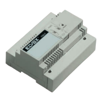
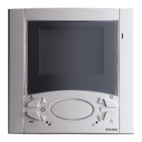
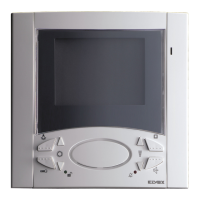
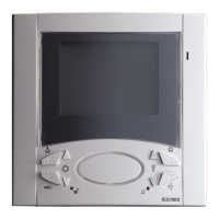
Monitor
type 6000
type 6003
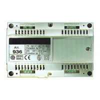
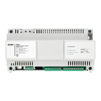
To power supply
type 6680
A - type 6153
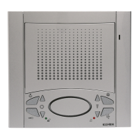
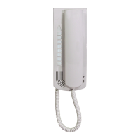
Interphone
type 6200
DESCRIPTION OF MODULE type 6153
Switching module type 6153 makes it possible to control the ringto-
ne volume or disable it, on interphones with call loudspeaker in the
PETRARCA series, type 6200 - 6201. The device also has two
LEDs , one for indicating that the ringtone is OFF (red indicator)
and one to indicate that the door lock is open (green indicator); the
use of these two devices requires additional connections as shown
in the wiring diagrams.
INSTALLING THE MODULE ON PETRARCA SERIES
INTERPHONES 6200 - 6201
- Open the interphone Fig. 1
- Snap off the plastic lamina by exerting pressure on it (Fig. 1B)
- Insert the card in its seat and fix it with the screw supplied (Fig. 2)
- Disconnect the loudspeaker wire from pin "A" on the interphone.
- Insert the removed wire onto the pin (CN2) on the card type 6153.
- Insert the wire pre-connected to terminal n° 6 of type 6153, on pin
"A" of the interphone (Fig. 3)
N.B. On terminal n° 7 of card type 6153, there is a wire to be used
for visual indication that the ringtone is disabled.
In position "0" (ringtone OFF) terminals
7 -10 are connected to the diode, thus enabling the red LED to
light.
Ringtone level selection
Position "0": ringtone OFF
Position "1": minimum volume
Position "2": medium volume
Position "3": maximum volume
Left
←
Right
→
Wiring diagram of call volume control module
without visual indicators
When the ringtone OFF visual indicator is
used (red LED) as well as the "lock open"
indicator (green LED), it is necessary to
power these diodes (up to a maximum of
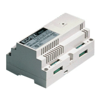
30) with the separate power supply type
6582. See diagrams on next page.


 To Next Page