2
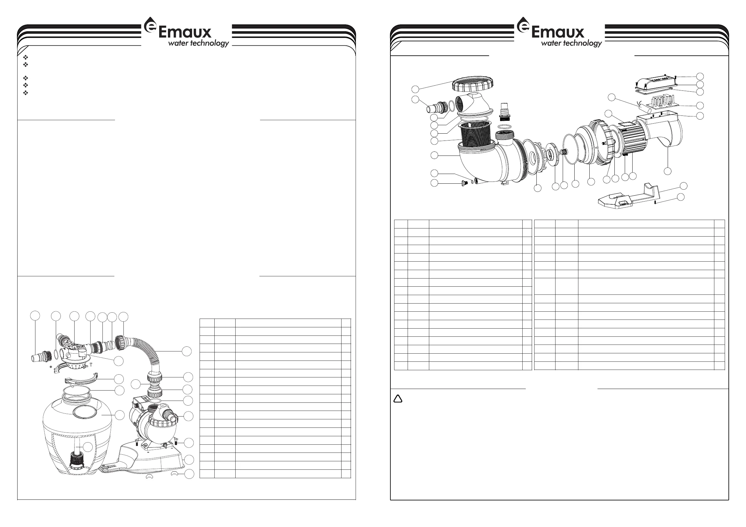
REPLACEMENT PARTS OF FILTER
1. Be sure correct amount of filter media sand is in tank and that all connections have been made and are secure.
2. Depress control valve handle and rotate to BACKWASH position. (To prevent damage to control valve seal,
3. Prime and start pump. Never tun pump dry! Running pump dry may damage seals,causing leakage and flooding!
Fill pump with water before starting motor. (be sure all suction and return lines are open), allowing the filter tank
to fill with water. Once water is flowing out of the waste line, run the pump for at least 1 minute. The initial
back-washing of the filter is recommended to remove any impurities or fine sand particles in the sand media.
4. Turn pump off and set valve to RINSE position. Start pump and operate until water in sight glass is clear, about
normal filter mode, filtering dirt particles from the pool water.
5. Adjust pool suction and return valves to achieve desired flow. Check system and filter for water leaks and tighten
6. Note the initial pressure gauge reading when the filter is clean. (It will vary from pool to pool depending upon the
initial "clean" pressure you noted, it is time to backwash the filter (see BACKWASH under filter and control
NOTE: During initial clean-up of the pool water it may be necessary to backwash frequently due to the unusually
INSTALL/START-UP OF FILTRATION
always depress handle before turning.)
1/2 to 1 minute. Turn pump off and set valve to FILTER position and restart pump.The filter is now operating in the
connections, bolts, nuts, as required.
pump and general piping system.) As the filter removes dirt and impurities from the pool water, the accumulation in the
filter will cause the pressure to rise and flow to diminish. When the pressure gauge reading is 1.5 bar, higher than the
heavy initial dirt load in the water.
valve functions).
AMU PUMP REPLACEMENT PARTS
Release all air from filter and piping system.
In a flooded suction system (water source higher than pump), pump will prime itself when suction and
discharge valves are opened.
If pump is not in a flooded suction system, unscrew and remove trap cover; fill trap and pump with water.
Clean and inspect Ring; re-install on trap cover.
Replace trap cover on trap; turn clockwise to tighten cover.
NOTICE: Tighten trap cover by hand only .Pump should prime now. Priming time will depend on vertical
length of suction lift and horizontal length of suction piping.
PRIMING PUMP
WARNINGS:
I
I
I
I
I
I
I
I
I
The Emaux pump must be connected to the main power supply by an approved and licensed electrician.
If the supply cord is damaged, it must be replaced by the manufacturer, service agent, or similarly qualified individuals to avoid hazards.
This appliance is not suitable for individuals (including children) with reduced physical, sensory, or mental capabilities or those lacking
experience and knowledge unless supervised or instructed by a person responsible for their safety.
Children should be supervised to stay away from the circulation system equipment and prevent them from playing with it
The maximum total head is 1 meter.
Contamination of the liquid may occur due to lubricant leakage.
The pool pump system must not be used unless a properly functioning safety suction and/or skimmer box specifically designed
for the swimming pool has been installed.
During pump startup, please stay away from the circulation system equipment. Before servicing the pool and spa water circulation system,
ensure that all system and pump controls are in the off position. Before starting the system pump, all system valves must be set to allow the
system water to return to the pool. Do not change the position of the filter control valve while the system pump is running.
The pump must be supplied with a residual current device (RCD) with a rated residual operating current not exceeding 30 mA.
!
3
AMU020TP AQUA-MINI Pump (with Timer & Pre-Filter)
AMU020P AQUA-MINI Pump (with Pre-Filter)
Plastic Pressure Gauge with O-Ring (28psi)
Clamp Lock with Screws & Nut
Lateral Assembly with Center Pipe
Part No.
Description
Key No.
QTY
1
2
3
4
5
6
7
8
9
10
11
12
13
14
15
16
11
2
6
5
17
28
24
1
3
4
6
7
8
9
10
11
12
13
14
15
16
17
18
19
27
5
21
20
22
23
25
26
2
Motor (AMU020TP/AMU020P) (220V/50Hz)(220V/60Hz)
Capacitor for AMU012TP/AMU012P&AMU016TP/AMU016P
(220V/50Hz,220V/60Hz)
Capacitor for AMU020TP/AMU020P(220V/50Hz,220V/60Hz)
32mm-38mm Union (Optional)
Impeller AMU020TP/AMU020P) (220V/50Hz)
Impeller AMU020P&TP(220V/60Hz)
Part No.
Description
Key No.
QTY
Part No.
Description
Key No.
QTY
 Loading...