Installation & Operating Instructions
EMC-DMA-2.0
Energy Management Consultants, 1550 La Follette Street, Fennimore, WI 53809
Tel. +1-608-822-3550 • Fax +1-608-822-3847 • E-mail: info@emccontrols.com • Web: www.emccontrols.com
Specications subject to change without notice.
rev. 04/15/19
43273_ins_DMA_2.0
2 of 4
Termination
Operation
All terminal blocks are removable/
pluggable connectors.
14 to 22 AWG wire is required for all
connections.
Power: 24 VAC or 24 VDC
(UL Listed Class 2 Power Source only)
Door Switch: Connection is not
polarized.
Auxiliary Relays: Can be connected
as either normally open (NO) or
normally closed (NC).
Buzzer: Remove the cover sticker
prior to use.
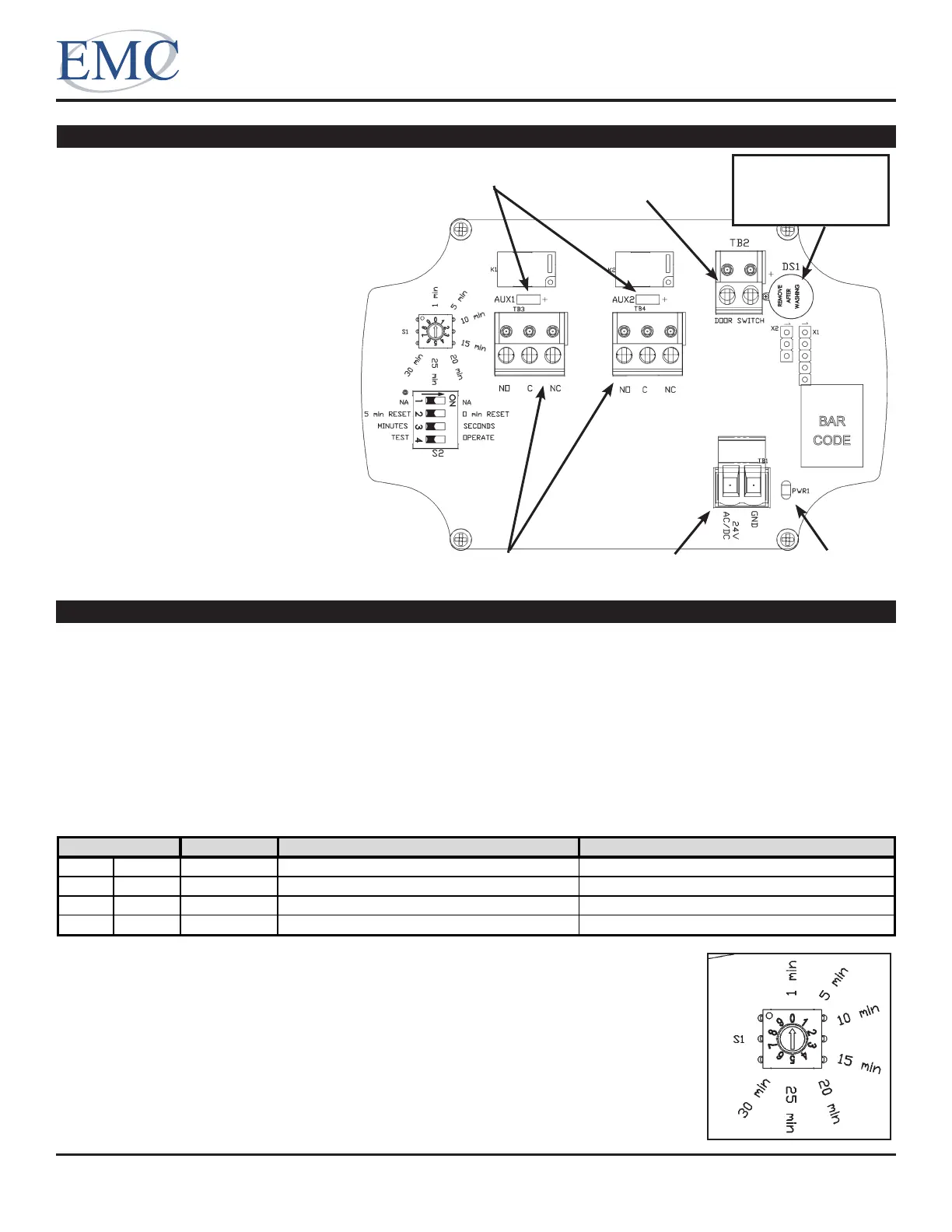
Fig. 3: DMA -2.0
Circuit Board
Basic Operation:
When the door opens, the Door Switch input terminals create an open circuit. The Door Status LEDs on the face
of the unit will change color, both Auxiliary Relays will energize (providing dry contact outputs), and both Auxiliary
Relay LEDs will illuminate. If the door stays open longer than the Door Timer Interval setting, the buzzer will sound.
Closing the door will de-energize both of the Auxiliary Relays, silence the buzzer if it is on, and change the color of
the Door Status LEDs.
The Auxiliary Relays are energized whenever the door is open and de-energized whenever it is closed.
The Door Status LEDs on the face of the unit change colors depending on the conditions listed in the table below.
Door Status Additional Condition User Action
Green Solid Closed
Amber Flashing Open Door timer interval has not been exceeded. Close the door when completed with your work.
Amber Solid Closed 5 minute Buzzer Reset Interval has not expired. Avoid opening the door until the LEDs turn green.
Red Flashing Open Door timer interval exceeded. Close the door as soon as possible.
Color
Door Status LEDs (located on the face of the unit)
Door Internal Timer:
The user can select how long the door can be continuously open before the buzzer
sounds and the status LEDS turn red. Figure 4 shows the allowable settings. If the
switch is in one of the blank positions, it uses 1 min.
Fig. 4: Door Timer
Interval Rotary
Switch (S1)
Auxiliary Relay
Connections
Power Connection Power On
LED (green)
Relay LEDs (red) Door Switch
Connection
Remove
Sticker Prior
to Use!
 Loading...