46 EMC VNX5400 Hardware Information Guide
I/O modules
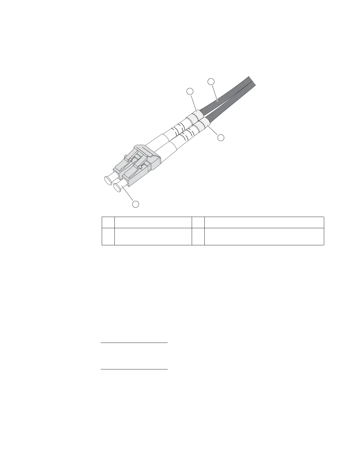
(connector ends), these cables will show a letter and numeral (for example A1 and A2 for
the TX and RX, respectively) or a white and yellow rubber gasket (jacket) for the send or
transmit (TX) and receive (RX) ends (Figure 31 on page 46).
Figure 31 Example of LC-type connectors
Storage processor I/O module types
Six I/O module types are supported by the Block, File, and Unified VNX5400 platform SP.
However, only four slots are supported per SP (A1 – A4 and B1 – B4) in the VNX5400
platform DPE. For more information, refer to the
Adding Storage Processor I/O modules
and SFPs to the DPE
document for the correct procedures to add an I/O module. This
procedure is available online at https://mydocs.emc.com/VNX/ and go to VNX tasks, then
select Add VNX hardware. Next, follow the steps in the wizard.
When adding new I/O modules, always install I/O modules in pairs—one module in SP A
and one module in SP B. Both SPs must have the same type of I/O modules in the same
slots.
1 Orange cable 3 Rubber gasket (jacket), receive (RX)
2 Rubber gasket (jacket), send or
transmit (TX)
4 Ferrule (connector end to SFP+ module)
3
1
2
4
CNS-001102

 Loading...


