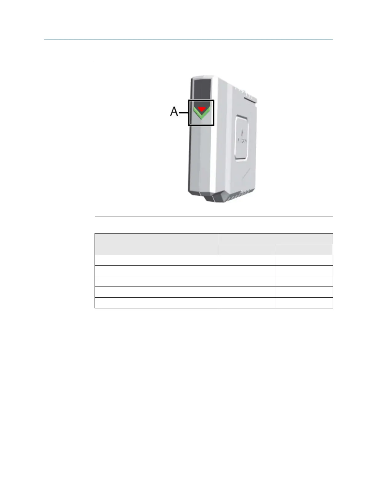
Figure 4-4: +24 V DC Power Module
A. Green and red LED for status indication, see Table 4-2
Table 4-2: Meaning of the LED indication
Event LED indication
LED Blinking pattern
Power Module active Green Solid
Power Module inactive Green Off
Input voltage is below 21.6 V DC Red Solid
Input voltage is above 26.4 V DC Red Solid
Input voltage is between 21.6 V DC and 26.4 V DC Red Off
4.3 Position of the mounting holes
The AMS Asset Monitor has four through holes without thread and four blind holes with a
standard M8 thread to mount the AMS Asset Monitor on a flat surface like a wall or on a
framework.
Installing AMS Asset Monitor hardware Installation Guide
March 2024 MHM-97923-PBF
26 MHM-97923-PBF, Rev. 2.10

 Loading...


