5.5.1 Connect the output signal wiring
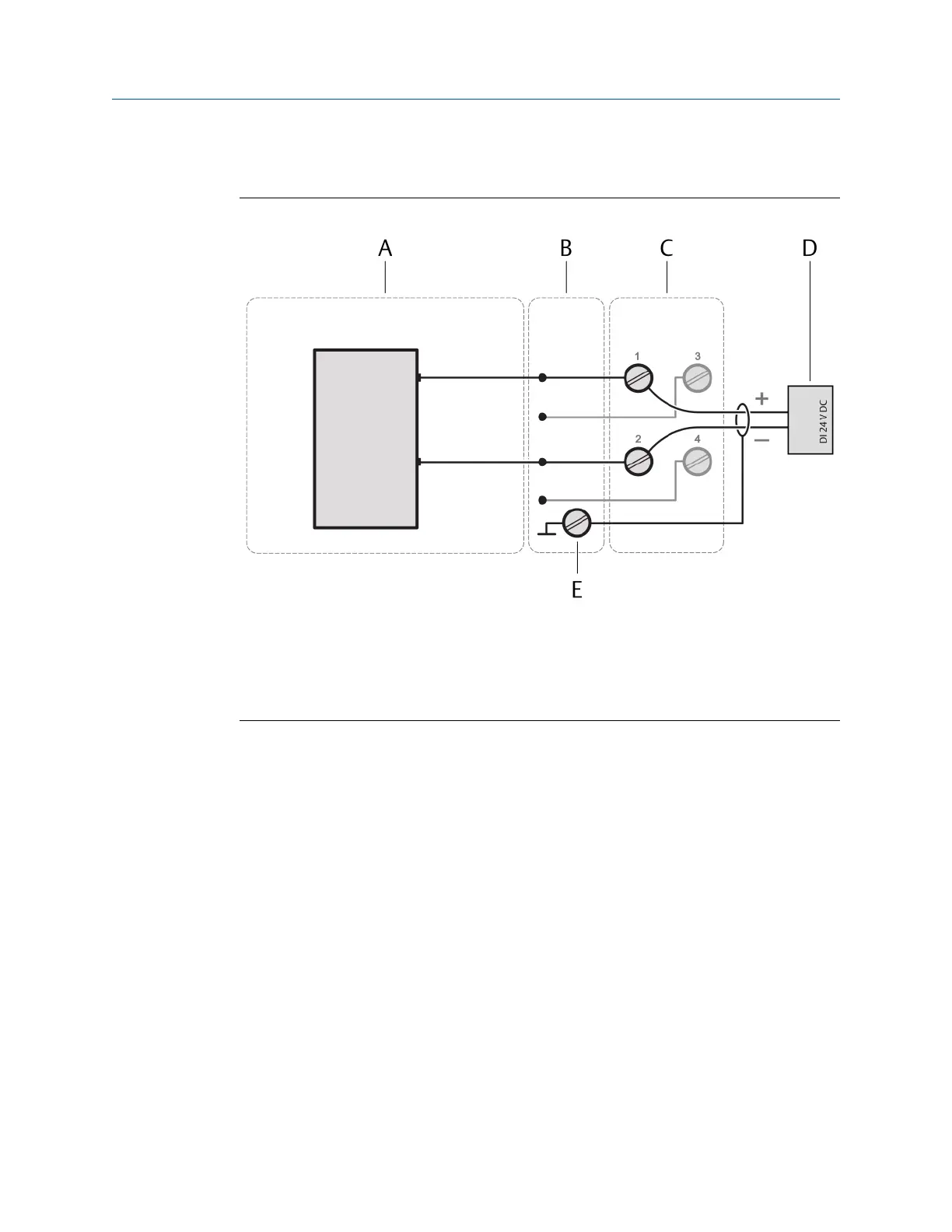
Figure 5-12: Signal connection
A. Digital Output DO 24 V DC High-Side CHARM
B. CHARM Baseplate
C. CHARM Terminal Block
D. Field device with digital input
E. Cable shield connection
Prerequisites
• Wire cutter
• Tool for removing the cable sheath
• Wire stripper
• Suitable screw driver for the CHARM Terminal Block screws
• Observe the hints in Wiring guidelines.
Procedure
1. At opened door, lead the signal cable through a cable gland close to the slot where
the CHARM to be connected is installed.
2. Strip the cable sheath at a length of approximately 200 mm.
3. Strip each wire at a length of approximately 10 mm.
4. Connect the wires to the CHARM Terminal Block.
• Connect terminal + of the digital input of the field device to terminal 1 of the
CHARM Terminal Block.
Installation Guide Installing CHARMs hardware
MHM-97923-PBF March 2024
MHM-97923-PBF, Rev. 2.10 55

 Loading...


