• Connect terminal - of the digital input of the field device to terminal 2 of the
CHARM Terminal Block.
• Connect the cable shield to a grounding terminal (see Grounding).
5. Ensure that the cable gland, where the signal cable is led through, is closed to keep
the IP protection class of the AMS Asset Monitor.
6. Continue with the installation or close the door (see Close the AMS Asset Monitor).
5.5.2 Connect the relay output wiring
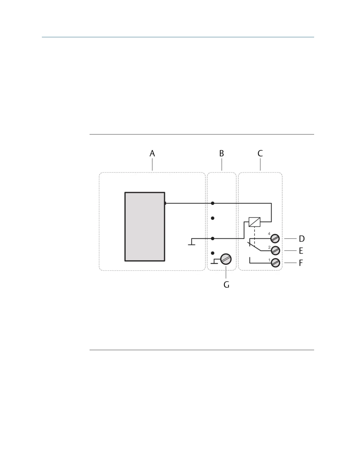
Figure 5-13: Relay output connection
A. Digital Output DO 24 V DC High-Side CHARM
B. CHARM Baseplate
C. CHARM Relay Output Terminal Block
D. Relay output: NC (normally closed)
E. Relay output: Common
F. Relay output: NO (normally open)
G. Cable shield connection
Prerequisites
• Wire cutter
• Tool for removing the cable sheath
• Wire stripper
• Suitable screw driver for the CHARM Relay Output Terminal Block screws
• Observe the hints in Wiring guidelines.
Installing CHARMs hardware Installation Guide
March 2024 MHM-97923-PBF
56 MHM-97923-PBF, Rev. 2.10

 Loading...


