DL8000 Preset Instruction Manual
I-2 Revised February-2016
Enhanced Start Communications (0x3B)
DanLoad 6000 .............................................. D-68
Error Codes ...................................................... D-90
Ethernet ............................................................ 3-36
Exception Codes ............................................... D-85
F
Failure
communication ............................................... D-2
Field Wiring
AC I/O ......................................... 3-21, 3-22, 3-23
AI ............................................................. 3-8, 3-9
AO ................................................................ 3-10
APM .............................................................. 3-24
DI .................................................................. 3-11
DO ................................................................ 3-15
DOR .............................................................. 3-16
PI .................................................................. 3-14
Figures
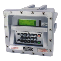
1-1. Typical DL8000 Load Rack ..................... 1-2
1-2. DL8000 (in Class I, Zone 1 Enclosure) ... 1-4
2-1. Standard DL8000 Enclosure ................... 2-2
2-2. Standard DL8000 Enclosure ................... 2-3
2-3. Bolt Tightening Sequence ....................... 2-5
2-4. Card Cage (with modules) ...................... 2-7
2-4. Class I Division 2 DL8000 Housing ......... 2-6
2-6. CPU Front View ...................................... 2-8
2-7. CPU Connectors ..................................... 2-9
2-8. License Key ........................................... 2-13
2-9. License Key Installation ........................ 2-14
2-10. DL8000 Operator Interface ................. 2-23
2-11. DL8000 Keypad .................................. 2-24
3-1. 12 Volt DC Power Input Module .............. 3-2
3-2. Typical I/O Module .................................. 3-3
3-3. Optional I/O Module Locations ................ 3-4
3-4. AI-12 Jumper J4 (Shown Set to +12V) ... 3-8
3-5. Analog Input Module Field Wiring ........... 3-8
3-6. AI-16 DIP Switches ................................. 3-9
3-7. Analog Output Jumper J4
(Shown Set to +12V) .................................. 3-10
3-8. Analog Output Module Field Wiring ...... 3-10
3-9. Discrete Input Module Field Wiring ....... 3-11
3-10. Pulse Input Jumper J4
(Shown Set to +12V) .................................. 3-13
3-11. Externally Powered Pulse Input Module
Field Wiring ................................................ 3-13
3-12. DL8000 Powered Pulse Input Module
Field Wiring ................................................ 3-14
3-13. Discrete Output Module Field Wiring .. 3-15
3-14. Discrete Output Relay Module Field
Wiring ......................................................... 3-16
3-15. RTD Sensor Wiring Terminal
Connections ............................................... 3-18
3-16. AC I/O DIP Switches ........................... 3-19
3-17. AC I/O Module (Output Field Wiring) .. 3-19
3-18. AC I/O Module (Input Field Wiring) ..... 3-20
3-19. Wiring with Multiple AC I/O Modules ... 3-22
3-20. Fuse Wiring with Multiple AC
I/O Modules ................................................ 3-23
3-21. Pulse Input Wiring on APM ................. 3-24
3-22. Micro Motion 7835/7845 Wiring on
APM ............................................................ 3-24
3-23. Generic Densitometer Wiring on
APM ............................................................ 3-24
3-24. Input Detector Wiring on APM ............. 3-24
3-25. Series Detector Switch (Normally Open)
Wiring on APM ........................................... 3-24
3-26. Series Detector Switch (Normally Closed)
Wiring on APM ........................................... 3-24
3-27. Independent Detector Wiring
on APM ....................................................... 3-25
3-28. Two-Pulse Turbine Pulse Input
Wiring on APM ........................................... 3-25
3-29. Pulse Output Wiring on APM .............. 3-25
3-30. DIP Switches on APM ......................... 3-26
3-31. Thermocouple Input Module Wiring .... 3-28
3-32. Ungrounded - Sheathed ...................... 3-29
3-33. Grounded ............................................ 3-29
3-34. Exposed, Ungrounded – Unsheathed . 3-29
3-35. HART-2 Module Input Point-to-Point
Wiring ......................................................... 3-32
3-36. HART-2 Module Input Multi-Drop
Wiring ....................................................... 3-32
3-37. HART-2 Module Output Wiring ........... 3-32
3-38. Communication Ports .......................... 3-33
3-39. RJ-45 Pin Out ...................................... 3-35
3-40. 10BASE-T Crossover Cable ............... 3-38
3-41. EIA-422/485 J4 Jumper ...................... 3-41
B-1. Modbus Configuration – General tab ...... B-2
B-2. Modbus Configuration – Scale
Values tab ................................................... B-5
B-3. Modbus Configuration – History
Table tab .................................................. B-9
B-4. Modbus Configuration - Registers
tab............................................................... B-14
B-5. Modbus Configuration - Master
Table tab .................................................... B-20
B-6. Modbus Configuration - Master
Modem tab ................................................. B-23
D-1. Modbus Registers ................................. D-73
E-1. DL8000 Operator Interface ..................... E-1
E-2. DL8000 Keypad ...................................... E-2
E-3. LCD Screen (Loading Mode) .................. E-5
E-4. Navigation Setup Option ....................... E-12
E-5. PINs Screen .......................................... E-13
E-6. Multiple Flow Rates with a Single
Meter Factor ............................................... E-60
E-7. Multiple Flow Rates with Multiple
Meter Factors ............................................. E-60
E-8. DO Module Field Wiring ........................ E-76
E-9. DI Module Field Wiring ......................... E-79
E-10. AO Module Field Wiring ...................... E-82
E-11. AI Modules Field Wiring ...................... E-86
E-12. AC I/O Module Output Field Wiring .... E-90
E-13. AC I/O Module Input Field Wiring ....... E-90

 Loading...


