Do you have a question about the Emerson Fluid Chiller and is the answer not in the manual?
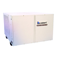
Detailed overview of the Liebert Process Fluid Chiller's components and system features.
Lists and describes optional components available for the chiller system.
Details the optional factory-installed refrigerant gauges and reservoir heater for the fluid reservoir.
Lists and describes accessory equipment shipped separately for customization and indoor installation.
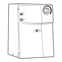
Explains the function, features, and application of the emergency water source module.
Describes the multi-point level switch, solenoid valve, and RCM4 monitor accessory.
Details the analog fluid pressure gauge for panel mounting and monitoring supply or return pressure.
Describes the brass body swing check valve used in fluid piping to prevent backflow.
Details the 2-1/2 inch dial thermometer for panel mounting and fluid temperature measurement.
Explains the brass body relief valve, set at 50 PSI, for installation in fluid piping.
Describes the bronze body balancing valve for flow balance, metering, and shut off.
Details the brass body 1/4 turn ball valve used for isolation of fluid piping components.
Explains the remote bulb thermostat for alarming when fluid temperature rises above design limit.
Describes the brass body flow switch that provides alarm contact when fluid flow falls below design limit.
Details the eight-point dry contact monitoring system used for remote monitoring and alarming.
Instructions for inspecting the unit for visible or concealed damage upon arrival.
Guidance on selecting an optimal location for the air-cooled chiller, considering security and airflow.
Instructions for connecting the chiller to the coolant loop, including valve and insulation requirements.
Steps for connecting the unit to the AC power source and field wiring according to codes.
Guidance on preparing and using ethylene or propylene glycol solutions for freezing protection.
Refers to the Operation section for the start-up checklist and procedure.
A comprehensive checklist of items to verify before starting the chiller unit.
Step-by-step instructions for safely energizing and starting the chiller unit.
Explains the general operational principles, system responses, and fan motor regulation.
Describes the transformer's role in providing 24 VAC for control circuit relays and contacts.
Details how to adjust the low pressure switch cut-out and cut-in settings for different fluids.
Instructions for setting the temperature control (thermostat) setpoint and differential.
Information on the non-adjustable high pressure switch that limits maximum discharge pressure.
Explains the function of the non-adjustable time delay relay that bypasses the low pressure switch.
Describes the function of the non-adjustable time delay relay preventing rapid compressor cycling.
Covers periodic inspections and maintenance of the refrigeration system components.
Details suction pressure variations, low pressure switch settings, and maximum operating pressures.
Discusses discharge pressure variations and the high pressure switch cut-out setting.
Explains how to determine and adjust superheat using the thermostatic expansion valve.
Explains TEV function and provides steps for adjusting superheat setting.
Details the function and adjustment procedure for the hot gas bypass valve.
Guidance on cleaning and maintaining the air-cooled condenser for optimal efficiency.
Information and procedures for replacing a faulty compressor unit.
Describes symptoms and causes of mechanical compressor failure, indicating motor attempt to run.
Discusses symptoms and causes of electrical compressor failure, indicating pungent odor and black oil.
Step-by-step procedure for replacing a compressor, including safety and recovery steps.
Information regarding the chilled fluid pump, including differential and suction pressure.
Explains pump differential pressure requirements and measurement for preventing motor overload.
Details minimum pump suction pressure requirements and checks for low pressure.
Information on the optional refrigerant gauges located in the unit exterior panels.
Describes the optional reservoir heater for maintaining fluid temperature during low ambient startups.
Explains the function of the coolant reservoir tank for reducing temperature fluctuations and expansion.
Describes the 8- and 10-ton chiller features, including dual compressors and heat exchangers.
Lists the eight gauges included with the 8- and 10-ton chillers for monitoring various parameters.
Explains the electronic hot gas bypass valve and controller for precise capacity control.
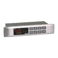
Instructions for setting the chiller temperature setpoint via potentiometer using a voltmeter.
Explains the circuit setter and ball valve for setting the desired system flow rate.
Table of symptoms, possible causes, and remedies for chilled fluid pump operational issues.
Table of symptoms, possible causes, and remedies for compressor operational issues.
Table of symptoms, possible causes, and remedies for refrigeration system operational issues.
Table of symptoms, possible causes, and remedies for condenser fan operational issues.
Checklist items for inspecting the air-cooled condenser's cleanliness, motor, and bearings.
Checklist items for inspecting the chilled water pump for leaks and proper operation.
Checklist item for inspecting the compressor for leaks.
Checklist items for inspecting electrical connections and operation sequence.
Checklist items for inspecting refrigerant lines, pressures, and valves.
List of fans and motors with part numbers and applicability across different ton models.
Lists model numbers for the emergency water source module based on chiller ton capacity.
Shows a typical system configuration diagram for the emergency water bypass module.
Details the normal operation and switchover sequence triggered by loss of flow or high temperature.
Lists and describes the key components of the emergency water source module, including RCM4 monitor.
Provides instructions for installing the module, including clearance and secure fastening.
Outlines periodic maintenance for the module, emphasizing monthly manual switchover verification.
Specifies the model number for the water level control module for 1.5 and 5 ton units.
Illustrates a typical system configuration diagram for the water level control module.
Explains the normal operation, fill sequence, and alarms for the water level control module.
Lists and describes the components of the water level control module, including RCM4 monitor and solenoid valve.
Provides instructions for installing the module, including reservoir switch and air vent.
Outlines periodic maintenance for the module, focusing on electrical system verification and supply line.