7-7
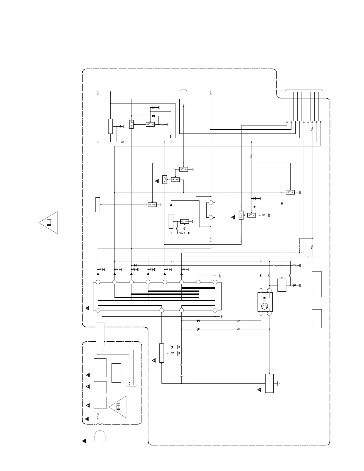
Power Supply Block Diagram
A71F3BLP
HOT
HOT
COLD
POWER SUPPLY CBA
INVERTER CBA
HOT CIRCUIT. BE CAREFUL.
TO DIGITAL
MAIN CBA UNIT
(CN3010)
Q602
SWITCHING
CONTROL
14
3 2
IC603
IC637
T601
CN601
TO INVERTER
BLOCK DIAGRAM
CN501
4
+3.3V
REG
HOT-GND 3
ACL 1
3
1
P-ON+9V 8
P-ON+5V 6,7
+2.5V 14
+4V
10-12
+15V 18
+2.5V 16
AL+3.3V 4
+5V/+12V-LCD 2,3
+35V 20
F501
4A/125V
LINE
FILTER
L503
AC501
AC CORD
LINE
FILTER
L502
BRIDGE
RECTIFIER
ACL
HOT-GND
D502 - D505
4A 125V
2
16
15
10
14
9
13
12
11
7
6
SHUNT
REG
Q601
SWITCHING
Q801
AMP+13V
P-ON+9V
P-ON-H
TO SYSTEM
CONTROL
BLOCK
DIAGRAM
AL+3.3V
CN301
+9V REG
Q639,Q640
Q641
Q638
Q637
Q644
JS632
Q635
Q633
JS661
Q636
SW +13V
Q632
Q631
Q643
23
JS612
Q650,Q651
Q652
SW +5V
CAUTION !
Fixed voltage (or Auto voltage selectable) power supply circuit is used in this unit.
If Main Fuse (F501) is blown , check to see that all components in the power supply
circuit are not defective before you connect the AC plug to the AC power supply.
Otherwise it may cause some components in the power supply circuit to fail.
For continued protection against risk of fire,
replace only with same type 4 A, 125V fuse.
CAUTION ! :
ATTENTION : Utiliser un fusible de rechange de même type de 4A, 125V.
4A/125V
NOTE:
The voltage for parts in hot circuit is measured using
hot GND as a common terminal.

 Loading...