22 PACMotion VFD AC Variable Speed Drive User Guide GFK-3111A
Removing the Terminal Cover
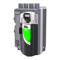
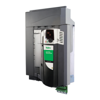
Figure 13: Frame Sizes 2 & 3 Figure 14: Terminal Cover Release Screws
Using a suitable at
blade screwdriver, rotate
retaining screws indicated
by arrows until the screw
slot is vertical.
Figure 15: Frame Size 4 Figure 16: Frame Size 5 Figure 17: Frame Sizes 6 & 7
Routine Maintenance
The drive should be included within the scheduled maintenance program so that the installation maintains a
suitable operating environment, this should include:
• Ambient temperature is at or below that set out in section Environmental on page 84.
• Heat sink fans freely rotating and dust free.
• The Enclosure in which the drive is installed should be free from dust and condensation; furthermore
ventilation fans and air lters should be checked for correct air ow.
Checks should also be made on all electrical connections, ensuring screw terminals are correctly torqued;
and that power cables have no signs of heat damage.

 Loading...


