RSTi-OM User Manual Section 5
GFK-3212A Jun 2021
Connecting Devices 48
Section 5: Connecting Devices
This section discusses connecting devices to the IOLM.
• Overview (Section 5.1)
• IOLM IO-Link Ports (Section 5.2)
5.1 Overview
The C/Q pin for the IO-Link ports in SIO mode for all models:
• DI – sinking input
The DI pin on the IO-Link ports for all models is a sinking input.
• DO – PNP/NPN (push/pull) output
5.2 IOLM IO-Link Ports
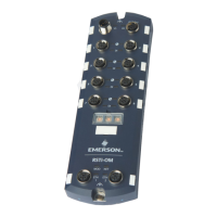
The IOLM provides eight IO-Link ports with M12, 5-pin female/A coded connectors. Each port has
robust over-current protection and short circuit protection on its L+/L- power output and C/Q IO-Link
signal. The pin-out for each IO-Link port is per the IO-Link standard and is provided in the following
table:
This table provides signal information for the IO-Link connectors.
Communication signal, which supports SDCI (IO-Link) or
SIO (standard input/output) digital I/O

 Loading...


