Disconnect wires from existing
switches only. Do not attempt to
disconnect any wires not already
connected to existing switches.
NOTE: Retrofit 3-way installations are
likely to include two traveler wires
between the two wall boxes. In new
construction, only one traveler wire is
required.
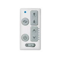
3. Before installing wall control, place wall
control in “OFF” mode by pushing
“ON/OFF” switch to the “OFF” position.
4. Install a wall control in the wall box
containing the “hot” wire first. Connect
one black wire of the wall control to the
“hot” wire. Securely connect wires with
wire connectors supplied.
5. Connect the other black wire of the wall
control to the remaining traveler wire(s)
in the wall box and secure with wire
connector supplied.
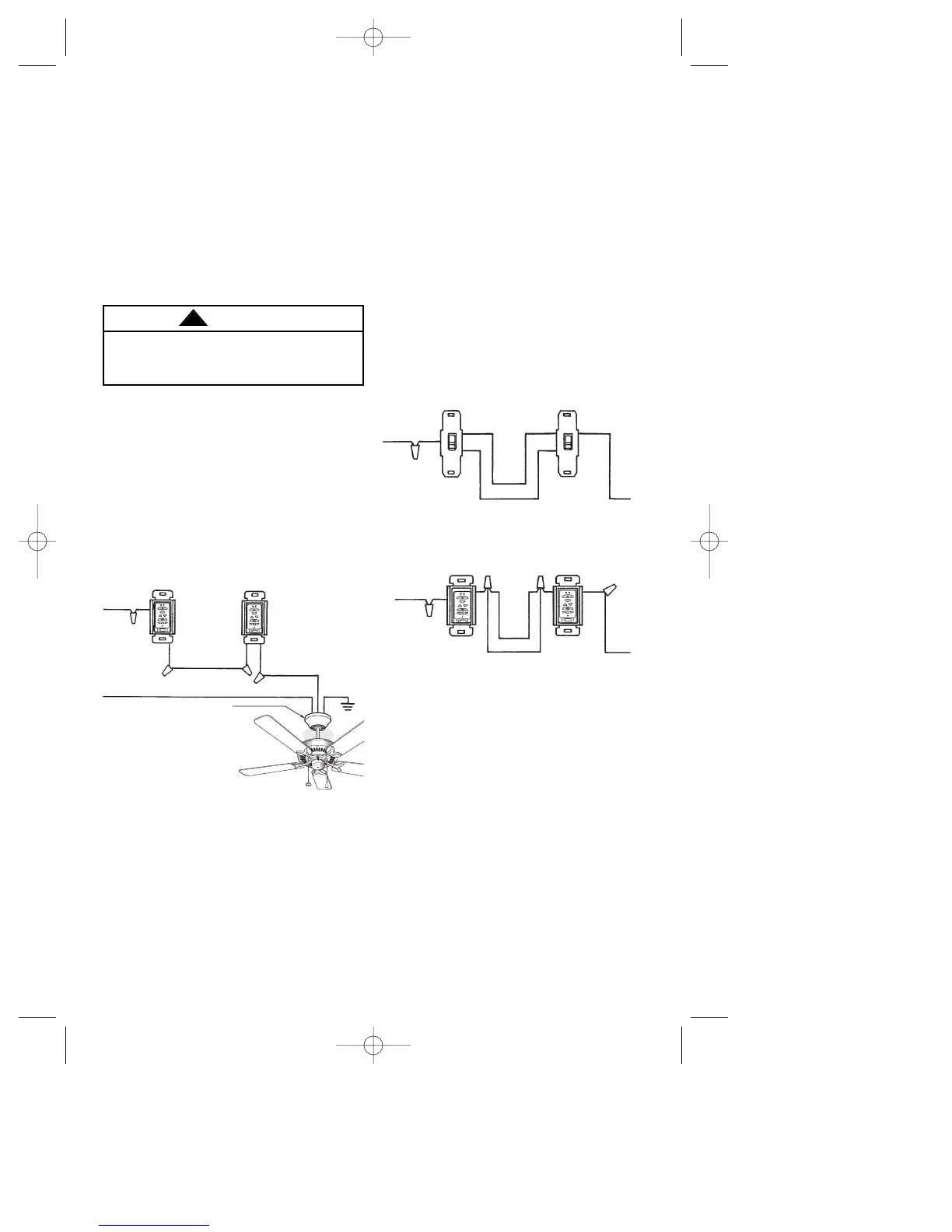
3-WAY WIRlNG DIAGRAM:
NEW CONSTRUCTION
6. Place wall control into wall box. Screw
in place and install decorator style
faceplate.
7. Next, install the other wall control into
the wall box containing the “load” wire.
Connect one black wire of the wall
control to the traveler wire(s) already
connected to the black wire (in the
other wall box). Secure with wire
connectors supplied.
7
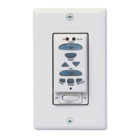
STANDARD WIRING FOR EXISTING
3-WAY CONTROLS
Figure 12
8. Connect one black wire of the wall
control to the “load” (black) wire and
secure with wire connector supplied.
9. Place the second wall control into the
wall box. Screw in place and install
decorator style faceplate (included).
Leave switch in “OFF” mode until fan
installation is completed.
10. Refer to fan Owner’s Manual to
complete fan installation.
NOTE: You must perform the Code
Learning Procedure for both wall
controls to be able to operate your fan
from both wall controls.
 Loading...