5 – 28
Section 5 • Maintenance/Service
VSS/VSR/VSM/VSH/VSSH Compressor • Installation, Operation and Service Manual • Emerson • 35391S
Gaterotor Disassembly
(All Compressors Except VSM 97-127
Compressors)
10. To perform gaterotor disassembly, remove gatero-
tor from compressor, see Gaterotor Assembly
Replacement procedure (All VSS-VSM Compressors
Except VSM 301-701 Compressors) or Gaterotor
Assembly procedure (VSM 301-701 Compressors
ONLY).
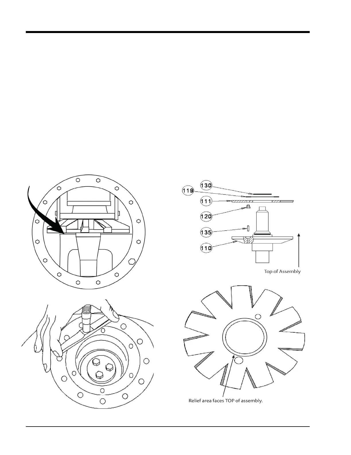
Gaterotor Blade Removal
11. Remove the snap ring and washer from the gatero-
tor assembly. Lift gaterotor blade assembly off the
gaterotor support, see Figure 5-31.
12. Check damper pin and bushing for excessive wear.
Replace if required.
Figure 5-30. Gaterotor and Shelf Clearance
Check for 0.003-0.004” (0.076- 0.102 mm) clearance
between gaterotor blade and partition.
Figure 5-31. Gaterotor Blade Assembly
blade and the shelf, rotate the gaterotor to nd
the tightest spot. It should be between 0.003-
0.004“ (0.076-0.102 mm). Make adjustments, if
necessary. It is preferable to shim the gaterotor
blade looser rather than tighter against the shelf,
see Figure 5-30.
8. After clearance has been set install a new O-ring
on bearing housing cover, install cover and tight-
en the bolts to the recommended torque value.
9. Install side cover with a new gasket. Tighten the
bolts to the recommended torque value. The
unit can then be evacuated and leak checked.

 Loading...


