Document Part # 026-4280 Rev 1 Page 4 of 33
©2022 Emerson Digital Cold Chain, Inc. This document may be photocopied for personal use.
Visit our website at www.climate.emerson.com for the latest technical documentation and updates.
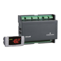
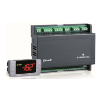
5.3. Keyboard Display CX660 or CH660
5.4. LAN Connection - Maximum of 8 Connections
To create a LAN connection and to a perform synchronized defrost (also called master-slave functioning):
1. Connect a shielded cable between terminals 38 [-] and 39 [+] for a maximum of eight (8) sections.
2. The Adr parameter is the number that identifies each electronic board. Address duplication is not permitted; in this case,
synchronized defrost and the communication with the monitoring system are not guaranteed (the Adr is also the
MODBUS address). See Figure 5-3 for an example of a properly configured LAN connection:
5.5. How to Connect the Monitoring System
Figure 5-2 - Keyboard Display
Figure 5-3 - LAN Connection
NOTE: If the LAN is connected properly, the green LED will be ON. If the LAN is not connected properly, a blinking LED will display.
The maximum allowed distance is 30m.
Figure 5-4 - Connecting the Monitoring System
The XM670/679K Board can operate also without
keyboard.
Polarity:
Terminal [34] [-]
Terminal [35] [+]
Use twister shielded cable AWG 18 or less in cases where
longer distance is required.
Max distance: 30 meters
1. Connect through terminals 36 [-] and 37 [+].
2. Use a shielded twisted cable (for example, Belden 8762 or CAT 5 cable).
3. The maximum allowable distance is 1 kilometer.
4. Do not connect the shield wire to the earth or ground terminals of the
device. Use insulation tapes to avoid accidental contacts.
 Loading...