J SET Page 3
Installation Instructions:
EMG Models: J, JA, J-CS SET (4 /5-STRING)
MASTER
TONE
FROM NECK PICKUP
FROM BRIDGE PICKUP
BATTERY
NEG (-)
MASTER
VOLUME
OUTPUT
T
R
S
OUTPUT CABLE
RED
RED
RED
GROUND
BRIDGE P/U
NECK P/U
OUTPUT
- 9V +
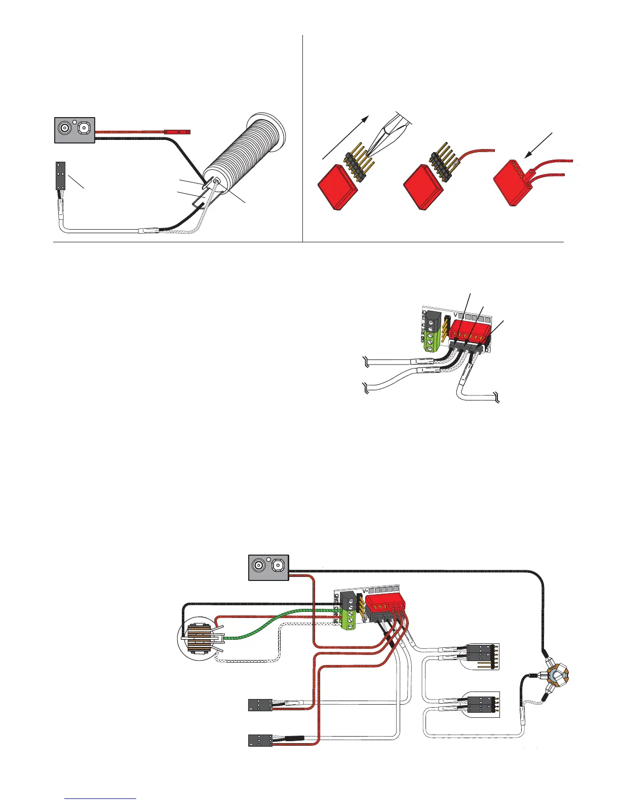
1) Install the Pickups and route the Pickup cables to the control cavity.
If the cables are too long, wind up the excess and keep it under the pickup.
2) Mount the Volume and Tone controls into the body.
Plug both Pickup cables onto the Pickup Buss (BLACK Shroud) as shown,
Refer to Diagram #6a
Bridge Pickup to position 1
Neck Pickup to position 2.
3) Plug a coax cable from the Pickup Buss (position 3) to the Master Volume
control as shown in Diagram #6b.
4) Plug a coax cable from the Master Volume to the Master Tone as shown.
5) Strip the insulation from the switch wires and Insert them into the GREEN
Terminal Block and tighten the screws with a small screwdriver.
The Bridge pickup goes to the BR Terminal
The Neck pickup goes to the NK Terminal
The Output of the switch goes to the O Terminal
If there is a ground wire coming from the switch, insert it into one of the black
terminals on the terminal block.
6) Plug the output cable onto the Master Tone control and connect the output
wires to the output jack by pushing the connectors on as shown.
WHITE wire onto the TIP (T) contact,
BLACK wire onto the SLEEVE (S) contact
BLACK Battery Negative wire onto the RING (R) contact.
7) Plug the RED Wires of the pickups onto the V+ Supply Buss (RED Shroud)
along with the RED of the battery clip.
Extra pins on the V+ Supply Buss are for EMG Accessories.
8) Put the battery in the insulating foam piece provided and place it securely in the
control cavity.
We suggest that you plug in the instrument and test it before closing the
control cavity.
Diagram #6b
2 Pickups
1 Master Volume
1 Master Tone
Toggle Style Switch
TIP
RING
SLEEVE
Diagram #4
FROM TONE
OR VOLUME
BATTERY
NEG (-)
RED to BATTERY BUSS
Soldering to the 152B Panel Jack:
If your instrument has a long Panel Jack like the one below
you will have to solder the output cable as shown.
Ground (Black) to the sleeve
Signal (White) to the Tip
Battery Negative (Black) to the Ring
- 9V +
Diagram #5
1
3
Soldering to the battery buss:
If your instrument has an older EMG Pickup you can solder the
pickup RED wire to the buss. Simply use some needle nose pliers,
pull out the V+ header and solder the RED Wire from the pickup(s)
to any of the pins and then re-insert the header into the housing.
2
BRIDGE PICKUP (POSITION 1)
NECK PICKUP (POSITION 2)
OUTPUT (POSITION 3)
TO MASTER TONE
NECK PICKUP
BRIDGE PICKUP
Installation (Two Pickup Guitars with Selection switch):
Guitars with two pickups and a selection switch will use the EMG B157 Pickup Buss
shown at the right in Diagram #6a.
The Pickup Buss is a convenient way to wire your guitar without soldering.
There is a separate sheet attached to these instructions that describes the
Pickup Buss in detail.
In all installations it’s best to find a place to mount the Pickup Buss in the control
cavity before starting. Then, after the cables are routed use the velcro to mount it
securely.
Diagram #6a
 Loading...