Installation Instructions:
EMG Model: PA2 (No Switch)
The PA2 requires a 1/4 inch hole (6.2mm) and the bushing length
is 5/16 inches long (8mm). Optimum control compartment body
thickness is less than 1/4 inch.
PA2 No Switch Instructions Page 2
Like all EMG Accessory products, the PA2 uses EMG’s 5-pin connector.
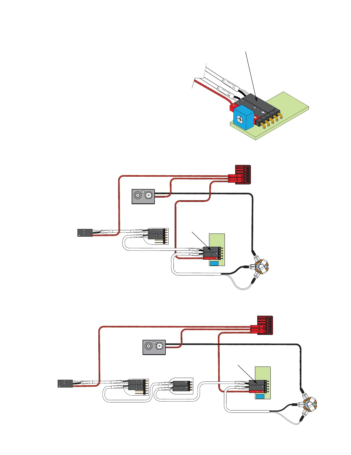
Diagram #1 to the right shows how the plug-in connectors are installed.
Be sure to reverse the input connector as shown. Keep in mind that all
of the EMG Accessory controls can be substituted for one another since
they all have buffered inputs and utilize the same 5-pin connnector.
Diagrams #2 and #3 illustrate installations that have a single pickup and
do not use a selection switch.
Pages 3 and 4 have diagrams that have 2 pickups and a selection switch,
or 3 pickups and use the B161 five position selection switch/buss.
If you have the B161, refer to that data sheet where more options
regarding the 3-pickup instruments are available.
Note: Reversed connector! Pins 1 and 2 are reversed.
Make sure the connectors are plugged on as shown.
Input
Volts +
Output
PA2
Diagram #2
One Pickup
One Volume
One PA2 Booster
OUTPUT
T
R
S
FROM PICKUP
BATTERY
NEG (-)
RED
RED
BATTERY
BUSS
OUTPUT CABLE
MASTER
VOLUME
- 9V +
RED
NOTE:
REVERSED
CONNECTOR
MASTER TONE
(PASSIVE)
Diagram #3
One Pickup
One Volume
One Master Tone (Passive)
One PA2 Control
OUTPUT
T
R
S
FROM PICKUP
BATTERY
NEG (-)
RED
RED
BATTERY
BUSS
OUTPUT CABLE
MASTER
VOLUME
- 9V +
RED
Diagram #1
PA2
NOTE:
REVERSED
CONNECTOR

 Loading...