Do you have a question about the emmeti POWER idroLAN and is the answer not in the manual?
| Brand | emmeti |
|---|---|
| Model | POWER idroLAN |
| Category | Controller |
| Language | English |
Example of single management setup for the device.
Example of centralized management setup for multiple devices.
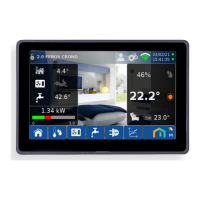
Description of the digital thermo-regulator and its electronic board.
Overview of the Emmeti IdroLAN system architecture and connections.
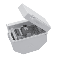
Detailed diagram and description of the Power IdroLAN card connections.
Important warnings and safety precautions for installation and maintenance.
Step-by-step instructions for installation and maintenance procedures.
Instructions for safe and compatible electrical connections.
Information on how to identify the device's electronic card.
Technical specifications including dimensions, protection grade, and power supply.
Procedure for fixing the electrical box to the unit.
Diagram for connecting LCD Console to multiple Power IdroLAN units.
Diagram for connecting Analog Console to multiple Power IdroLAN units.
Instructions for connecting the RS 485 network for system communication.
Details on the main fan outputs (S1-S2-S3) and speed control.
Explanation of fan operating algorithms: Continuous and Thermostat modes.
Fan activation logic based on water temperature for heating/cooling modes.
Function to mitigate air stratification by activating the fan.
Logic to delay fan start/stop to prevent cold air or overheating.
Analog output for proportional fan control using 0-10Vcc input.
Control of hot/cold electro-thermal valves (On-Off or PWM).
Analog outputs for modulating hot/cold valves using 0-10Vcc input.
Function to prevent valve blockage due to prolonged inactivity.
Description and connection of the ambient temperature sensor.
Details on the water temperature sensor (WS) installation and use.
Functionality of the Economy contact for energy saving and setpoint adjustment.
Window contact input for standby mode and antifreeze function.
Fault Motor contact input for detecting fan overheating and signaling alarms.
Setting the season changeover mode: Manual, Centralized, or Ambient Temp.
Configuration for SLAVE units on the Local-bus network.
Detailed list of configurable parameters for the device.
Device state where outputs are disabled, except antifrost and Modbus.
State where the controller manages ambient comfort.
Energy saving mode activated by occupancy or night time.
Explanation of LED indicators for different operating modes and states.
Table showing Input/Output parameters, their registers, and ranges.
List and description of abnormal states and error codes (alarms).