CG Drives & Automation Sweden AB, Box 222 25, SE-250 24 Helsingborg, T +46 42 16 99 00
www.emotron.com/www.cgglobal.com
CG Drives & Automation, 01-5328-01r1, 2015-04-17
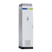
Fig. 3 Default toggle loop
Overview of the main menu
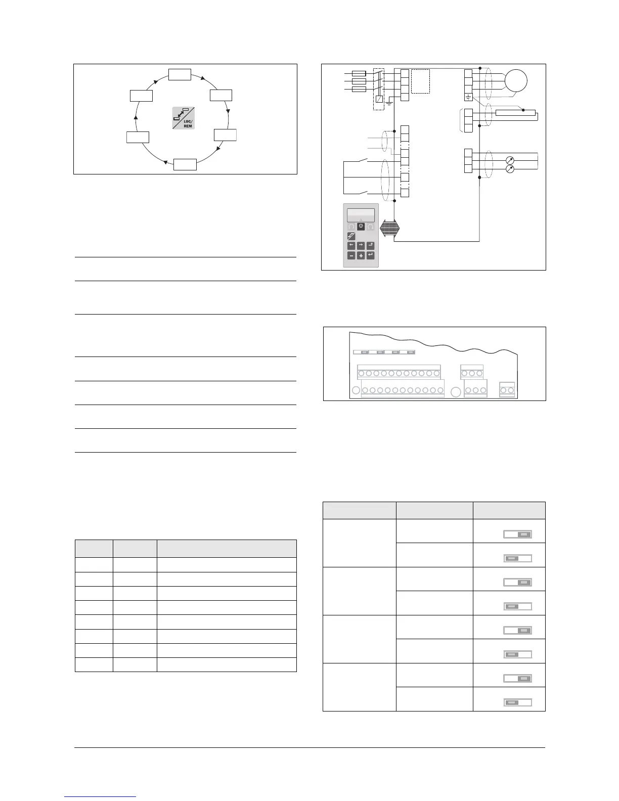
Control connections
Fig. 4 Connection example.
Input configuration with the switches
Fig. 5 Location of switches and connectors.
The switches S1 to S4 are used to set the input configuration
for the 4 analogue inputs AnIn1, AnIn2, AnIn3 and AnIn4
as described in table 2. See Fig. 5 for the location of the
switches.
[100] Preferred view. Displayed at power-up. Shows
actual values (default: speed and torque).
[200] Main Setup. Main settings to get the inverter opera-
ble e.g. motor data, autoreset and language.
[300] Process and Application parameters. Settings more
relevant to the application such as Reference
Speed, torque limitations, PID control settings, etc.
[400] Shaft power monitor and process protection. The
monitor function enables the AC drive to be used as
a load monitor to protect machines and processes
against mechanical overload and underload.
[500] Inputs/outputs and virtual connections. All settings
for analogue and digital inputs and outputs.
[600] Logical functions and timers. All settings for condi-
tional signals are entered here.
[700] View operation and status. Viewing all the operatio-
nal data like frequency, load, power, current, etc.
[800] View Trip log. Viewing the last 10 trips in the trip
memory.
[900] Service information and AC drive data. Electronic
type label for viewing the software version and AC
drive type.
Table 1 Description of used terminals.
Terminal Name Function (Default)
2 AnIn 1 Process reference, default: speed
7 Common Signal ground
9 DigIn 2 RunR; rotation right
11 +24V +24VDC Supply voltage
12 Common Signal ground (If desired)
13 AnOut 1 Min speed to max speed (If desired)
14 AnOut 2 0 to max torque (If desired)
22 DigIn 8 Reset
 Loading...