EMX Industries, Inc. Tech support: 216-834-0761 4/8
IRB-RET_Rev2.0_080619 technical@emxinc.com
8. The IRB-RET is housed in a NEMA 4X enclosure. To ensure the integrity of the enclosure, make sure
the gasket is present, the cover is properly seated, and the cover screws are tight. The wiring to
the enclosure must enter via a UL listed watertight fitting such as a strain relief or watertight
conduit connector.
9. Tighten the mounting screws on the bracket.
10. Verify that the photoeye and reflector are aligned and apply power.
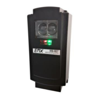
11. Place an obstruction (ex. hand) between the photoeye and reflector. The green LED on the
receiver will flash and the red LED will turn off. Remove the obstruction and the green LED and
red LED will turn on.
12. Check the operator control board and verify that the safety input is recognized by the operator.
Test the beam with an obstruction between transmitter and reflector at multiple distances to
confirm proper operation.
13. Follow the gate or door operator manufacturer’s installation instructions and safety checks to
verify that the photoeye is operating properly.
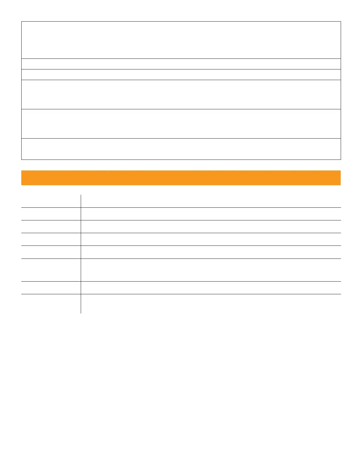
Configuration Settings and Wiring Diagrams
Transmitter power input (non-polarized)
Receiver power input (non-polarized)
Isolated pulse output collector
Isolated pulse output emitter
Normally open contact, relay output shown in energized state (power on,
no obstruction) when properly aligned to the reflector
Normally closed contact, relay output shown in energized state (power on,
no obstruction) when properly aligned to the reflector.
 Loading...