Cerabar M HART Installation
Endress+Hauser 13
Threaded connection, flush-mounted diaphragm
P01-PMP41xxx-06-09-xx-xx-001
Fig. 9: The flush-mounted version is screwed into the process thread with max. 50 Nm ± 5 Nm (at AF 27).
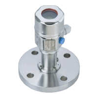
3.3.2 Installation instructions for devices with diaphragm seals –
PMP46, PMP48
!
Note!
• The Cerabar M with a diaphragm seal is screwed in, flanged or clamped, depending on the type
of diaphragm seal.
• Together, a diaphragm seal and the pressure transmitter form a closed, calibrated system which
is filled with oil. The filling hole is sealed and should not be opened.
• Do not clean or press the diaphragm of the diaphragm seals with hard or pointed objects.
• Do not remove diaphragm protection until shortly before installation.
• When using a mounting bracket, sufficient strain relief must be ensured for the capillaries in order
to prevent the capillary from buckling (bending radius ≥ 100 mm).
• Please note that the hydrostatic pressure of the liquid columns in the capillaries can cause zero
point shift. You can correct this zero point shift → see Page 29, Section 6.2.5 "Position adjustment
- only display (bias pressure)" (onsite operation) or via communication → see Page 33,
Section 6.3.7 "Position adjustment - only display (bias pressure)".
• Please note the application limits of the diaphragm seal filling oil as detailed in the Technical
Information for Cerabar M TI399P, "Planning instructions for diaphragm seal systems" section.
In order to obtain more precise measurement results and to avoid a defect in the device, mount the
capillaries as follows:
• Vibration-free (in order to avoid additional pressure fluctuations)
• Not in the vicinity of heating or cooling pipes
• Insulate if the ambient temperature is below or above the reference temperature
• With a bending radius of ≥100 mm.
21
G ½
ø26
G ½
ø50
13
21
max. Druckfestigkeit
100 bar
–Einschweißadapter
Bestell-Nr.:52002643
– mit3.1 Abnahmeprüfzeugnis
Bestell-Nr.:52010172
Viton-Dichtung
O-Ring 14 x 1,78
Viton oder NBR
SW 27

 Loading...


