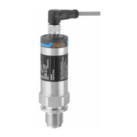
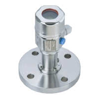
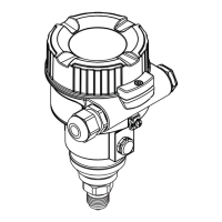
Ceraphant PTP31B, PTP33B Electrical connection
Endress+Hauser 21
6.3 Connection conditions
6.3.1 Cable specification
For valve plug: < 1.5 mm
2
(16 AWG) and Ø3.5 to 6.5 mm (0.14 to 0.26 in)
6.4 Connection data
6.4.1 Load (for devices with analog output)
The maximum load resistance depends on the terminal voltage and is calculated according
to the following formula:
[ ]W
20 30
10
0
1022
587
152
U
[V]
1
2
R
R
L
L
max
max
A0031107
1 Power supply 10 to 30 V DC
2 R
Lmax
maximum load resistance
U
B
Supply voltage
When excessively high load:
• Output of the fault current and display of " S803 "
• Periodic review whether error condition may be left
6.5 Post-connection check
Is the device or cable undamaged (visual check)?
Do the cables comply with the requirements ?
Do the cables have adequate strain relief?
Are all the cable glands installed, firmly tightened and leak-tight?
Does the supply voltage match the specifications on the nameplate?
Is the terminal assignment correct ?
If required: Has protective ground connection been established ?
If supply voltage is present, is the device ready for operation and do values appear on the display module or
is the green LED lit on the electronic insert?
 Loading...


