Installation Deltabar FMD71, FMD72
20 Endress+Hauser
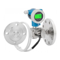
5.6 Installing the sensor modules
5.6.1 General installation instructions
• The nameplate on the sensor module specifies where the sensor module is typically
installed:
HP (bottom)
LP (top)
For further information, see the "Function" section → 13.
• Due to the orientation of the sensor modules, there may be a shift in the zero point, i.e.
when the vessel is empty or partially full, the measured value does not display zero.
You can correct this zero point shift: see the "Commissioning without an operating menu"
→ 42or the "Position adjustment"→ 47 section.
• Always install the sensor module HP below the lowest measuring point.
• Always install the sensor module LP above the highest measuring point.
• Do not mount the sensor modules in the filling curtain or at a point in the tank which
could be affected by pressure pulses from an agitator.
• Do not mount the sensor modules in the suction area of a pump.
• The adjustment and functional test can be carried out more easily if you mount the
sensor modules downstream of a shutoff device.
• If a heated sensor module is cooled during the cleaning process (e.g. by cold water), a
vacuum develops for a short time, whereby moisture can penetrate the sensor through
the pressure compensation (3). If this is the case, mount the sensor with the pressure
compensation (3) pointing downwards.
• Keep the pressure compensation and GORE-TEX® filter (3) free from contamination.
• Do not clean or touch process isolating diaphragms with hard or pointed objects.
A0017512
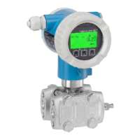
5.7 Mounting sensor modules with PVDF installation
coupling
L
WARNING
Risk of damage to process connection!
Risk of injury!
‣
Sensor modules with PVDF process connections with threaded connection must be
installed with the mounting bracket provided!

 Loading...