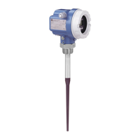
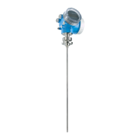
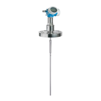
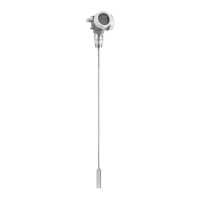
Caution!
•
Applications in hazardous areas: electrostatic charging, e.g. rubbing clean, must be
avoided for standard PTFE and PTFE-clad antennas.
•
Always tighten the locking screw, since this connects the antenna to the ground
potential of the housing.
Nozzle
•
There is no restriction on nozzle
diameter provided that the length is
less than or equal to the inactive length.
•
Max. nozzle length hmax
100 mm for 100 mm inactive length,
250 mm for 250 mm inactive length.
•
The alignment mark on the flange
should point towards the tank wall.
•
After mounting, the housing can be
turned through 350° for convenient
access to the display and connection
compartment. The locking screw must
be loosened before turning.
•
Tighten the locking screw after turning.
Threaded connection
•
The hexagonal nut (AF 60) is used to
screw the transmitter in position.
•
Use e.g. a PTFE tape to seal the
process connection.
•
The alignment point on the threaded
connection should point towards the
tank wall.
•
After mounting, the housing can be
turned through 350° for convenient
access to the display and connection
compartment. The locking screw must
be loosened before turning.
•
Tighten the locking screw after turning.
BA171Y18
ground terminal
locking screw
datum point of
measurement
h
max
100 mm
or
250 mm
beam
launched
here
mark points to
tank wall
max. level
use spring
washers for
cladded
flange
inactive length
BA171Y19
mark points to
tank wall
max. level
datum point of
measurement
locking screw
ground terminal
sealing tape
h
max
100 mm
or
250 mm
beam
launched
here
inactive length
Caution!
Micropilot FMR 231 Chapter 2 Installation
Endress+Hauser 11

 Loading...


