4 Operation
4.1 On-site operation
For the F12 housing, the operating elements are located within the transmitter housing
and can be operated when the cover is open. The T12 housing has a separate display
compartment which also can be opened in hazardous areas. The Micropilot has four
keys and an LED.
•
The LED flashes when an entered value is registered as well as during the
suppression of interference echoes. During operation it remains off.
•
The device keys allow the basic calibration of the Micropilot, but are deactivated
when the operating and display module VU 330 is connected.
Operation without the
VU 330
The function of the device keys when the operating and display module is not connected
is summarised in the table below. The two keys must always be pressed simultaneously.
The keys are used as follows, see Chapter 5:
Terminal
V H
V+ H
–
+
–
+
BA171Y26
bargraph
(current output/edho quality)
indicator
communication
fault
Operating and display module VU 330
matrix position
green LED
device
operating
keys
measured
not present with housing
T12
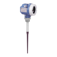
Fig. 4.1
Operating elements of
Micropilot FMR 231
Keys Function
Reset to factory settings, see Chapter 7.9
Empty calibration, see Chapter 5
Full calibration, see Chapter 5
False echo suppression, see Chapter 5
Lock parameter entry, see Chapter 5
Unlock parameter entry, see Chapter 5
+
+
__
Chapter 4 Operation Micropilot FMR 231
16 Endress+Hauser
 Loading...


