Commuwin IIA full description of the operating program Commuwin II is to be found in operating
instructions BA 124F. All Commuwin II functions are supported. The "envelope curve"
cannot be displayed. The transmitter is configured either via the operating matrix or the
graphic interface.
ConnectionThe table summarises the Commuwin connections,
Note!
•
Micropilot transmitters with HART interface can also be configured on site via the
keys. If the device keys are used to lock the matrix, then parameters cannot be
entered remotely via communication.
•
The Micropilot FMR 231 device description Version 2.0 is required for operation with
Commuwin II, see Operating Instructions BA 124F.
V1
V Calibration0
8.00
EMPTY CALIBRATION
7.50
FULL CALIBRATION
0
LINEARISATION
1
ECHO SUPPRESSION
1
TA BL E N O.
7.2
SUPPRESSION DIST.
0
ENTER LEVEL
27
ECHO QUALITY
67.5%
MEASURED VALUE
V Linearisation2
V Ent. calibration3
V4
V5
V6
V Service7
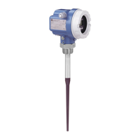
FMR 231
BA171E31
Fig. 4.4
Device menu in Commuwin II
Note!
Interface Hardware Server Live list
HART Commubox 191 set to HART
Computer with RS-232C port
HART Connected device only
FXN 672 interface module
Gateway for MODBUS,
PROFIBUS, INTERBUS, FIP etc.
Computer with RS-232C port or
PROFIBUS card
ZA 673 for
PROFIBUS
ZA 672 for
others
List of all connected Rackbus
devices – select the FXN 672 via
its bus address
Micropilot FMR 231 Chapter 4 Operation
Endress+Hauser 19
 Loading...


