Operating conditions (cont.)
Environment
Operating temperature
range
F12 housing: Standard –40°C...+80°C; EEx ia (T6) –40°C...+50°C
T12 housing: Standard –40°C...+80°C; EEx e (T6) –40°C...+50°C
For other temperature classes see appropriate certificate
Limiting temperature
range
–40°C...+80°C
Storage temperature –40°C...+80°C
Ingress protection Housing: IP65, NEMA 4X (open housing: IP20, Nema 1)
Antenna: IP68, NEMA 6P
Climate class IEC 68 part 2-30 GPC
Immunity to
temperature change
IEC 68 part 2-14 Nb (1K/min across temp. range)
Vibrational resistance EN 60 068-2-64
Electromagnetic
compatibility
Interference Emission to EN 61326, Electrical Equipment Class B
Interference Immunity to EN 61326, Annex A (Industrial) and NAMUR
Recommendation NE 21 (EMC)
A standard installation cable is sufficient if only the analogue signal is used.
Use a screened cable when working with a superimposed communications
signal (HART/Intensor).
Medium
Process temperature
range
PTFE antenna –40°C...+150°C; see page 5
PPS antenna –20°C...+120°C, see page 5; for CIP max. 5 min. at 150 °C
Process pressure range –1...16 bar gauge, PTFE with uncladded flange 40 bar gauge, see page 5
Properties and effects
of medium
Medium must have a minimum relative dielectric constant of 1.4, see page 7
Changes in dielectric constant have no effect on measurement
Mechanical construction
Housing
Material Aluminium, seawater-resistant, chromated and powder-coated
Terminal compartment F12 housing (EEx ia): sealed compartment in electronics housing
T12 housing (EEx e): separate increased-safety compartment
T12 housing (XP): separate explosion-proof compartment
Cable and conduit
entries
Pg 13.5 (gland supplied), ½ NPT, M 20x1.5, ½ BSP (G ½) internal thread
Cable See Electrical Connection, page 12
Process connection
Type Threaded connection 1 ½ NPT or 1 ½ BSPT (R 1 ½ DIN 2999)
Flanges DN50, DN80, DN100 and ANSI/JIS equivalents, page 54
Sanitary couplings: dairy, Tri-clamp and aseptic
Material 1.4435 (SS 316 L), PTFE cladded 1.4435, PVDF, depending on version
Wetted-parts See Table on page 5
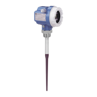
Antenna
Dimensions PPS: 360/510 mm, PTFE 390/540 mm, see page 48
Material PPS, PTFE/1.4435 (SS 316L)
Seal PPS antenna: Viton O-ring; PTFE antenna: conical seal
Weight (with housing) With thread approx.2.5 kg; with flange approx. 2.0 kg + flange weight
User interface
Keypad 4 keys for reset, calibration, and system security
Indication Green LED indicates data entry (externally visible)
Optional VU 330
operating and display
unit
4 ½ digit LCD (parameter), with alphanumeric matrix location indication
4 keys for data entry, parameter readout and system security
Foreign system interface HART or PROFIBUS-PA, depending on version
Chapter 9 Technical Data Micropilot FMR 231
50 Endress+Hauser
 Loading...


