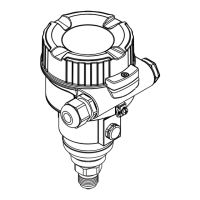
Gammapilot FMG50 HART Electrical connection
Endress+Hauser 15
A0028908
1 Block diagram of HART connection
1 Device with HART communication
2 HART resistor
3 Power supply
4 Multimeter or ammeter
Power supply
• Non-Ex: supply voltage: 16 to 35 VDC
• Ex i: supply voltage: 16 to 30 VDC
The HART communication resistor of 250 Ω in the signal line is always necessary in the
case of a low-impedance power supply.
The voltage drop to be taken into account is:
Max. 6 V for 250 Ω communication resistor
6.1.2 Rated cross-section
Protective ground or grounding of the cable shield: rated cross-section > 1 mm
2
(17 AWG)
Rated cross-section of 0.5 mm
2
(AWG20) to 2.5 mm
2
(AWG13)
6.2 Connecting the device
L
WARNING
‣
Please refer to the separate documentation on applications in hazardous areas for the
safety instructions
For optimum electromagnetic compatibility, the potential matching line should be as
short as possible and at least 2.5 mm
2
(14 AWG) in cross-section.
Connecting cables should be routed away from the housing from below to prevent
moisture from penetrating the connection compartment. Otherwise, a drip loop should
be provided or a weather protection cover should be used.
Please follow the enclosed installation instructions if a G1/2 entry is used.
Housing thread
The thread of the electronics and connection compartment is coated with lubricant
varnish.
Avoid additional lubrication.

 Loading...


