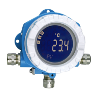
TMT162
Endress+Hauser 11
Sensor transmitter matching
Resistance thermometers have high linearity. However, every sensor has an individual temperature resistance
characteristic curve. This characteristic curve must be described as accurately as possible in order to achieve a
high level of accuracy in the linearization of the measured values in the transmitter. The TMT162 allows you
to utilize two methods:
• Customer-specific linearization
Using PC configuration software or the HART
®
handheld, the device can be programmed with sensor-
specific curve data. Once the sensor-specific data has been entered, the device utilizes this to generate a
custom curve. Readwin
®
2000 software supports by calculating sensor-specific curves.
• Callendar - Van Dusen coefficients
The Callendar - Van Dusen equation is described as:
where A, B and C are constants, commonly referred to as Callendar - Van Dusen coefficients. The precise
values of A, B and C are derived from the calibration data and are specific to each RTD sensor.
The process involves programming the device with curve data for a specific RTD, instead of using the standard
curve.
Sensor transmitter matching using any of the above methods substantially improves the temperature
measurement accuracy of the entire system. This is as a result of the transmitter using the sensor’s actual
resistance vs. temperature curve data instead of the ideal curve data.
Repeatability 0.0015% of the physical input range (16 Bit). Resolution A/D conversion: 18 Bit
Influence of supply voltage
(HART
®
)
≤ ±0.005%/V deviation from 24 V, related to the full scale value
Long-term stability ≤ 0.1 °C/year (≤ 0.18 °F/year) or ≤ 0.05%/year
Data under reference conditions. % relates to the set span. The larger value applies.
Influence of ambient
temperature (temperature
drift)
Total temperature drift = input temperature drift + output temperature drift
Physical input range of the sensors
10 to 400 Ω Cu10, Cu50, Cu100, Polynom RTD, Pt50, Pt100, Ni100, Ni120
10 to 2000 Ω Pt200, Pt500, Pt1000, Ni1000
-20 to 100 mV Thermocouple type: C, D, E, J, K, L, N, U
-5 to 30 mV Thermocouple type: B, R, S, T
R
T
R
0
1ATBT
2
C T 100–()T
3
++ +[]=
Effect on the accuracy when ambient temperature changes by 1 K (1.8 °F):
Input 10 to 400 Ω 0.001% of measured value, min. 1 mΩ
Input 10 to 2000 Ω 0.001% of measured value, min. 10 mΩ
Input -20 to 100 mV 0.001% of measured value, min. 0.2 μV
Input -5 to 30 mV 0.001% of measured value, min. 10 μV
Output 4 to 20 mA typ. 0.001% of span (maximum value = 1.5 x typ. value)
Typical sensitivity of resistance thermometers:
Pt: 0.00385 * R
nominal
/K Cu: 0.0043 * R
nominal
/K Ni: 0.00617 * R
nominal
/K
Example Pt100: 0.00385 x 100 Ω/K = 0.385 Ω/K
Typical sensitivity of thermocouples:
B: 10 μV/K C: 20 μV/K D: 20 μV/K E: 75 μV/K J: 55 μV/K K: 40 μV/K
L: 55 μV/K N: 35 μV/K R: 12 μV/K S: 12 μV/K T: 50 μV/K U: 60 μV/K

 Loading...


