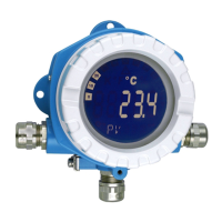
TMT162
Endress+Hauser 15
Human interface
Display elements
T09-TMT142ZZ-07-00-00-xx-001
LC display of the field transmitter (illuminated, pluggable in 90°−stages)
1: Bar graph display in 10 % stages with indicators for overranging/underranging
2: 'Caution' display
3: Unit display K, °F, °C or %
4: Measured value display - height of digits 20.5 mm (0.81")
5: Status and information display
6: 'Communication' display
7: ’Programming disabled’ display
Operating elements No operating elements are present directly on the display to prevent manipulation.
Remote operation Remote operation via:
•HART
®
protocol
• FOUNDATION Fieldbus™
• PROFIBUS
®
PA
°C
°F
%
K
10
0
20
30
40
50
60
70
80
90
100
1
2
3
4
5
6
7
HART
®
FOUNDATION Fieldbus™
PROFIBUS
®
PA
Jumpers J1, J2 and J3 for the hardware setup can be found
in the electronics compartment.
T09-TMT162ZZ-19-00-00-xx-001
Hardware setup
J1 Write lock
J2 Failure Mode (only if microcontroller fails)
J3 For reduced power supply voltage (11 V to 8 V)
without display
T09-TMT162ZZ-19-00-00-xx-002
Hardware setup
1: DIP switch for write lock; simulation (precondition
for FOUNDATION Fieldbus™ simulation mode)
2: DIP switch for PROFIBUS
®
device address
3: Electrical connection display and service interface
(CDI)
FAIL MODE
HI
TRANSMITTER SECURITY
J3
J2
J1
LO
OFF
ON
PROFIBUS
ADDRESS
SIM(FF)
WRITE
LOCK
ON
OFF
2
1
Software
64
32
16
8
4
2
1
3

 Loading...


