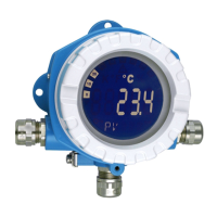
TMT162
Endress+Hauser 5
Output
Output signal
Resistance transmitter Resistance Ω 10 to 400 Ω
10 to 2000 Ω
10 Ω
100 Ω
Thermocouples (TC)
to IEC 584 part 1
to ASTM E988
to DIN 43710
Type B (PtRh30-PtRh6)
1)
2)
Type E (NiCr-CuNi)
Type J (Fe-CuNi)
Type K (NiCr-Ni)
Type N (NiCrSi-NiSi)
Type R (PtRh13-Pt)
Type S (PtRh10-Pt)
Type T (Cu-CuNi)
Type C (W5Re-W26Re)
Type D (W3Re-W25Re)
Type L (Fe-CuNi)
Type U (Cu-CuNi)
0 to +1820 °C (32 to 3308 °F)
-270 to +1000 °C (-454 to 1832 °F)
-210 to +1200 °C (-346 to 2192 °F)
-270 to +1372 °C (-454 to 2501 °F)
-270 to +1300 °C (-454 to 2372 °F)
-50 to +1768 °C (-58 to 3214 °F)
-50 to +1768 °C (-58 to 3214 °F)
-270 to +400 °C (-454 to 752 °F)
0 to +2320 °C (32 to 4208 °F)
0 to +2495 °C (32 to 4523 °F)
-200 to +900 °C (-328 to 1652 °F)
-200 to +600 °C (-328 to 1112 °F)
500 °C (900 °F)
50 °C (90 °F)
50 °C (90 °F)
50 °C (90 °F)
50 °C (90 °F)
500 °C (900 °F)
500 °C (900 °F)
50 °C (90 °F)
500 °C (900 °F)
500 °C (900 °F)
50 °C (90 °F)
50 °C (90 °F)
• Internal cold junction (Pt100)
• Accuracy of cold junction: ± 1 °C (± 1.8 °F)
• Max. sensor resistance 10 kΩ (if sensor resistance is greater than 10 kΩ, error message as per NAMUR NE89)
3)
Voltage transmitter (mV) Millivolt transmitter (mV) -20 to 100 mV 5 mV
1) Significant measuring error increase for temperature lower than 300 °C (572 °F).
2) When operating conditions are based on a large temperature range, the TMT162 offers the ability to split the range. For example, a Type S or R thermocouple
can be used for the low range and a Type B can be used for the upper range. The TMT162 is then programmed to switch at a predetermined temperature.
This allows for utilization of the best performance from each individual thermocouple and provides 1 output that represents the process temperature. Note:
the dual sensor option must be included in the order code for the HART
®
protocol. Two sensor inputs are already provided as standard if the FF and PA
protocol are selected.
3) Basic requirements NE89: detection of increased sensor resistance (e.g. corrosion of contacts or wires) of TC or RTD/4-wire.
Type of input Designation Measuring range limits Min. span
HART
®
Analog output 4 to 20 mA, 20 to 4 mA
Signal encoding FSK ± 0.5 mA via current signal
Data transmission rate 1200 baud
Galvanic isolation U = 2 kV AC (input/output)
FOUNDATION Fieldbus™
Signal encoding FOUNDATION Fieldbus™ H1, IEC 61158-2, Manchester Bus Powered (MBP)
Data transmission rate 31.25 kBit/s, voltage mode
Galvanic isolation U = 2 kV AC (input/output)
PROFIBUS
®
PA
Signal encoding PROFIBUS
®
PA as per EN 50170 volume 2, IEC 61158-2, Manchester Bus
Powered (MBP)
Data transmission rate 31.25 kBit/s, voltage mode
Galvanic isolation U = 2 kV AC (input/output)

 Loading...


