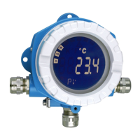
iTEMP TMT162 Operating options
Endress+Hauser 23
6.1.1 Display and operating elements
Display elements
°C
°F
%
K
10
0
20
30
40
50
60
70
80
90
100
!
1
2
3
4
5
6
7
A0034101
14 LC display of the field transmitter (backlit, attachable in 90° stages)
Item No. Function Description
1 Bar graph display In increments of 10% with indicators for underranging and
overranging.
2 'Caution' symbol This is displayed when an error or warning occurs.
3 Unit display K, °F, °C or % Unit display for the internal measured value displayed.
4 Measured value display, digit
height
20.5 mm
Displays the current measured value. In the event of an error
or warning, the corresponding diagnostics information is
displayed. → 36
5 Status and information
display
Indicates which value is currently shown on the display. Text
can be entered for every value. In the event of an error or a
warning, the sensor input that triggered the error/warning is
also displayed where applicable, e.g. SENS1
6 'Configuration locked' symbol
The 'configuration locked' symbol appears when configuration
is locked via the hardware or software
7 'Communication' symbol
The communication symbol appears when HART®
communication is active.
Local operation
NOTICE
‣
ESD - electrostatic discharge. Protect the terminals from electrostatic discharge.
Failure to observe this may result in destruction or malfunction of parts of the
electronics.
Hardware write protection and the proof test can be activated via a DIP switch or button on
the electronics module. When write protection is active, parameters cannot be modified. A
key symbol on the display indicates that the write protection is on. Write protection
prevents any write access to the parameters.

 Loading...


