Product description Liquiline System CA80SI
12 Endress+Hauser
3.3 Equipment architecture
3.3.1 Slot and port assignment
The electronics configuration follows a modular concept:
• Several slots are provided for electronics modules.
• These slots are numbered consecutively in the housing. Slots 0 and 1 are always reserved
for the basic module.
• Each electronics module has one or more inputs and outputs or relays. Here they are all
collectively known as "ports".
• Ports are numbered consecutively per electronics module. The software recognizes the
ports automatically.
• Outputs and relays are named according to their function, e.g. "current output", and are
displayed with the slot and port numbers in ascending order.
Example:
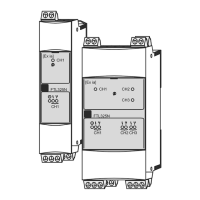
"Current output 2:1" shown on the display means: slot 2 (e.g. AOR module) : port 1
(current output 1 of the AOR module)
• Inputs are assigned to measuring channels in the ascending order of "slot:port number"
Example:
– "SP1: shown on the display means:
Sampling point SP1 is assigned to analyzer measuring channel 1.
– "CH1: 1:1 pH glass" shown on the display for sensors means:
Channel 1 (CH1) is slot 1 (basic module) : port 1 (input 1) and a pH glass sensor is
connected here.

 Loading...