14
Cable specification
Max. cable cross-section: 2.5 mm
2
(i14 AWG), GND 4 mm
2
(i12 AWG)
Supply voltage
Sensor connection Explanation of abbreviations in the following diagrams:
!
Note!
• Cable colours indicated as per IEC 757 (see CD-ROM).
• You must connect shielded connections and terminals with functional earth ()) (there is no protective earth
(*) for plastic housings).
• Since inductive conductivity sensors work with magnetic fields, avoid any magnetic interferences.
a0002378
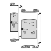
View in device (CPU module)
a0004062
Wiring diagram
Current output 4 to 20 mA without Hart
®
:
Current output 4 to 20 mA with Hart
®
:
PROFIBUS / FOUNDATION Fieldbus:
(max.22mA)
12.5 to 30 V DC
12.5 to 30 V DC
1))
9 to 32 V DC (non-hazardous location) /
9 to 17.5 V DC (hazardous location)
1) Permissible residual ripple acc. to IEC 60381-1:1985 3.3: <100 mVpp in the frequency range of
50 Hz to 3 kHz
Abbreviation Meaning
pH Signal from pH membrane glass
Ref Signal from reference electrode
Src Source
Drn Drain
PM Potential matching
U
+
Digital sensor supply
U
–
Com A
Digital sensor communication
Com B
ϑ Temperature signal
d.n.c. Do not connect!

 Loading...